Sealing device

A sealing device and side sealing technology, which is applied in engine sealing, bearing assembly, transportation and packaging, etc., to achieve the effects of improving sealing performance, stabilizing magnetic properties, and suppressing the increase in manufacturing costs

Inactive Publication Date: 2009-04-22
NOK CORP
View PDF1 Cites 8 Cited by
  • Summary
  • Abstract
  • Description
  • Claims
  • Application Information

AI Technical Summary

Problems solved by technology

[0007] However, the status quo is that the pulse generating ring 105 used to form a magnetic rotor encoder in the past, such as Figure 9 Shown in , only suitable for oil slinger 104 of sealing device 100

Method used


Image

  • Sealing device
  • Sealing device
  • Sealing device

Examples


Embodiment Construction

[0047] Best Mode for Carrying Out the Invention

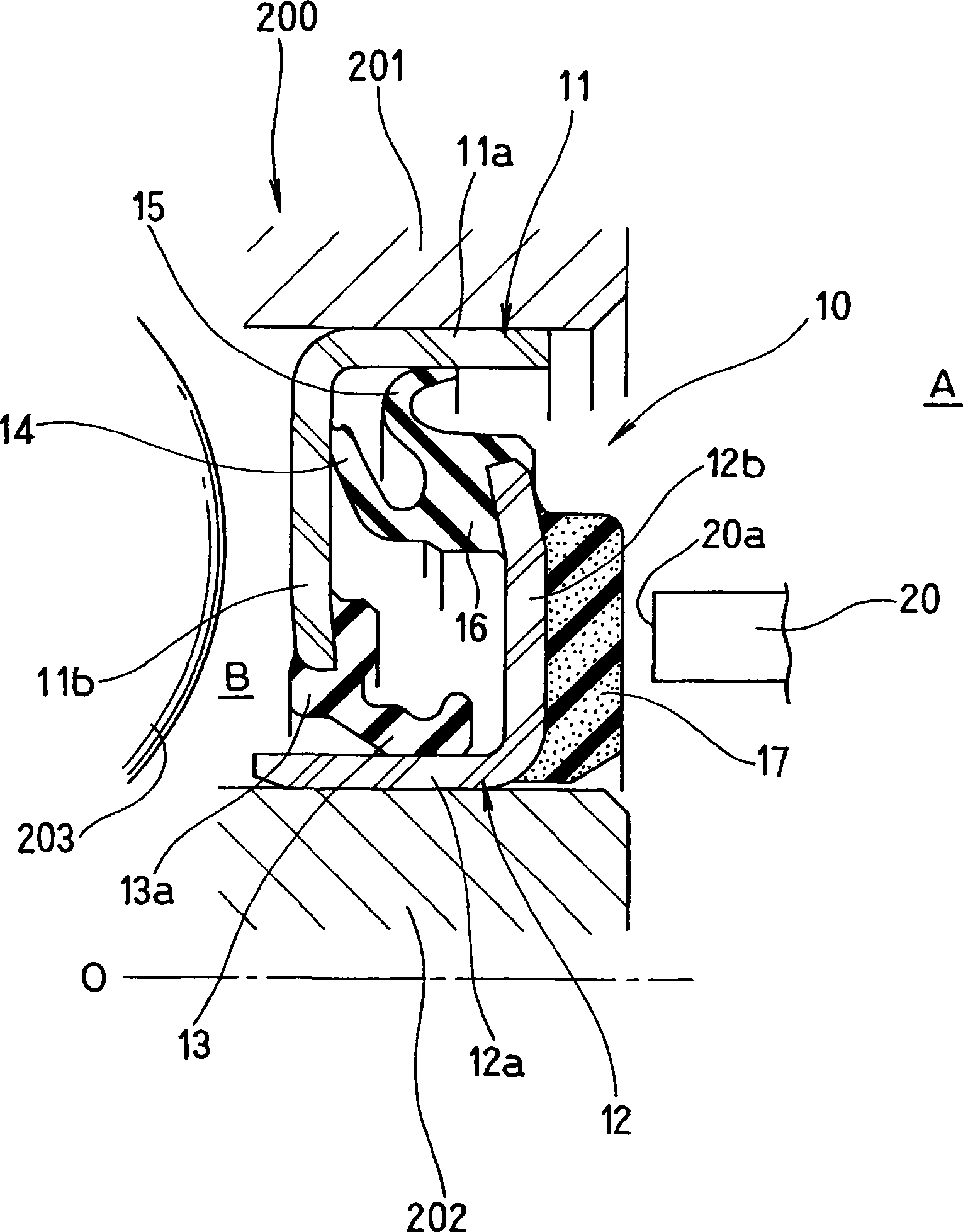
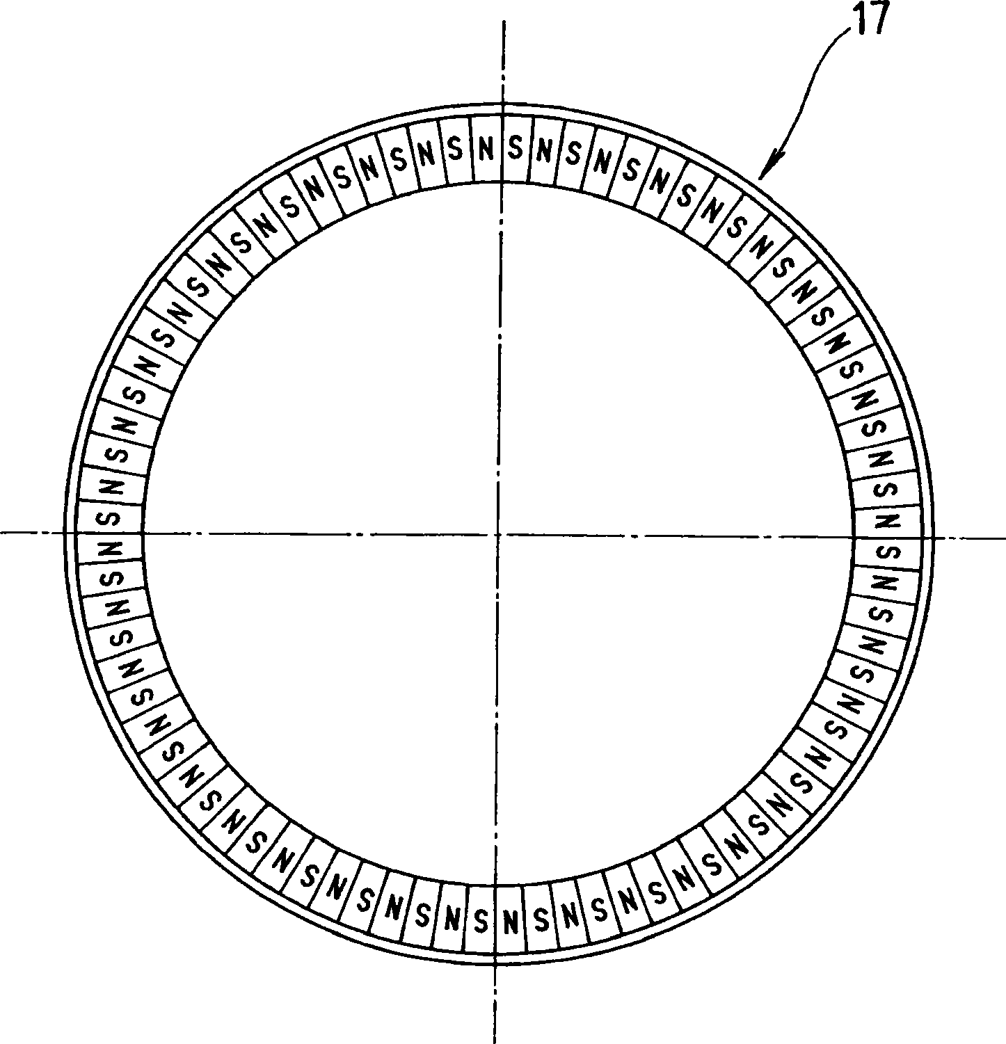
[0048] Preferred embodiments of the sealing device according to the present invention will be described below with reference to the drawings. figure 1 A cross-sectional view showing the sealing device according to the first embodiment of the present invention cut on a plane passing through the axis O, figure 2 It is an explanatory diagram showing an example of a pulsar ring magnetization pattern.

[0049] exist figure 1 In , reference numeral 200 is a bearing that rotatably supports a wheel in a vehicle suspension device, and a plurality of steel balls 203 are interposed between an outer wheel 201 and an inner wheel 202 arranged concentrically with the inner periphery thereof. Here, the outer ring 201 is non-rotating and corresponds to a stationary side member described in claim 1 , and the inner ring 202 rotates with an unshown shaft and corresponds to a rotating side member described in claim 1 .

[0050] The sealing de...


PUM


Abstract

A sealing device having a stationary-side installation ring tightly fitted into and fixed to an outer peripheral stationary-side member, a rotation-side installation ring tightly fitted into and fixed to an inner peripheral rotation-side member, a stationary-side lip provided on the stationary-side installation ring and whose forward end is made to be slidably in intimate contact with the rotation-side installation ring, rotation-side lips formed integrally with the rotation-side installation ring and slidably in intimate contact with the stationary-side installation ring, and a pulser ring formed of a synthetic resin or rubber-like elastic material mixed with magnetic powder, formed integrally with the rotation-side installation ring (12), and magnetized in multiple poles. On the outer periphery of the pulser ring, a flange is extended positioned on the outer side of the rotation-side lips and closely facing the stationary-side member or the stationary-side installation ring. The sealing device with the pulser ring has excellent sealing ability.

Description

technical field [0001] The present invention relates to a sealing device for sealing the outer periphery of a rotating body, and more particularly to a pulsar ring for a rotor encoder for detecting rotation. Background technique [0002] Figure 8 It is a cross-sectional view taken along a plane passing through the axis O, showing a sealing device that seals a bearing of a wheel suspension for an automobile. This sealing device 100 is also called a hub seal, and is assembled between the ends of the outer ring 201 and the inner ring 202 of the bearing 200 to prevent muddy water from entering the bearing inner B from the outer A of the bearing. [0003] That is to say, in Figure 8 The sealing device 100 shown in , includes a metal mounting ring 101 press-fitted to the inner peripheral surface of the outer ring 201 of the bearing 200, and a side seal lip 102 and a radial seal lip 103 integrally provided with the mounting ring 101. The seal lip 102 and the radial seal lip 103 ...

Claims


Application Information

Patent Timeline
Patent Type & Authority Applications(China)
IPC IPC(8): F16C33/78F16C33/80F16C41/00F16J15/32F16J15/3232F16J15/326
CPCF16J15/326F16C33/7879F16C41/007F16C2326/02F16C33/78F16C33/80F16C41/00F16J15/32
Inventor 小林直人
Owner NOK CORP
Why Eureka
Try Eureka