Squirrel-cage induction motor

An induction motor and cage-type technology, applied in asynchronous induction motors, electrical components, electromechanical devices, etc., can solve the problems of rising rotor manufacturing costs, high melting point of copper, and inability to use die-casting aluminum machines, etc., and achieve the goal of suppressing the rise of manufacturing costs Effect

Active Publication Date: 2014-06-04
SUMITOMO HEAVY IND LTD
View PDF13 Cites 1 Cited by
  • Summary
  • Abstract
  • Description
  • Claims
  • Application Information

AI Technical Summary

Problems solved by technology

[0005] However, copper has a higher melting point than aluminum, so die casting is difficult, and conventional aluminum die casting machines cannot be used
In addition, the manufacturing cost of the rotor also increases due to the use of copper

Method used


Image

  • Squirrel-cage induction motor
  • Squirrel-cage induction motor
  • Squirrel-cage induction motor

Examples


Embodiment Construction

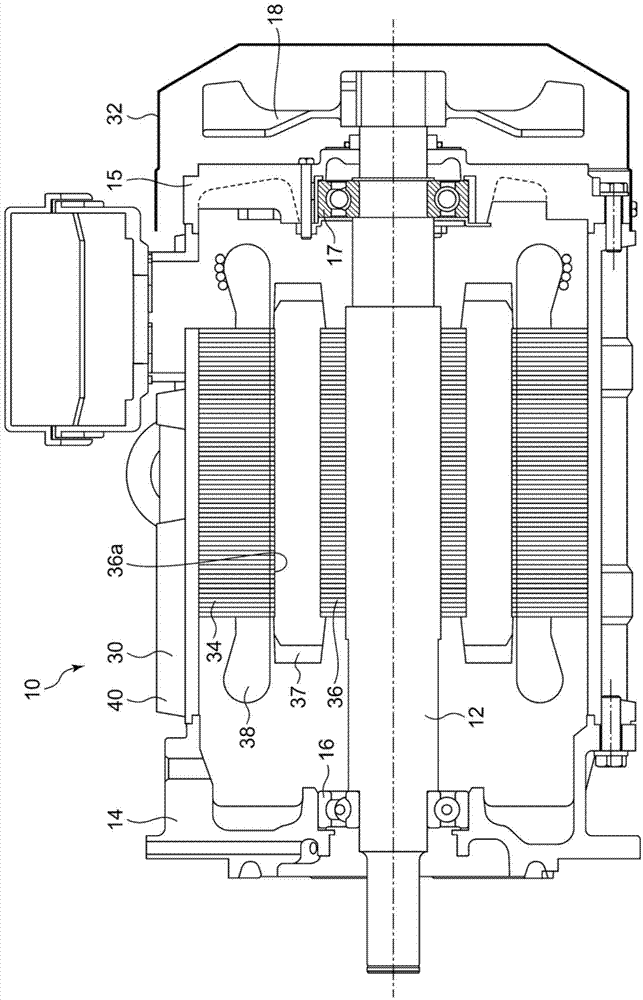
[0015] figure 1 It is a cross-sectional view when the cage-type induction motor 10 is cut along a vertical plane including the central axis.

[0016] The stator 34 is formed by laminating a plurality of thin-plate-shaped (for example, thickness 0.5 mm) electromagnetic steel sheets that are punched out in the same shape. The stator 34 is fitted to the inner periphery of the frame 30 by, for example, shrink fitting. A coil 38 of copper wire is wound on a plurality of slots formed in the stator 34 .

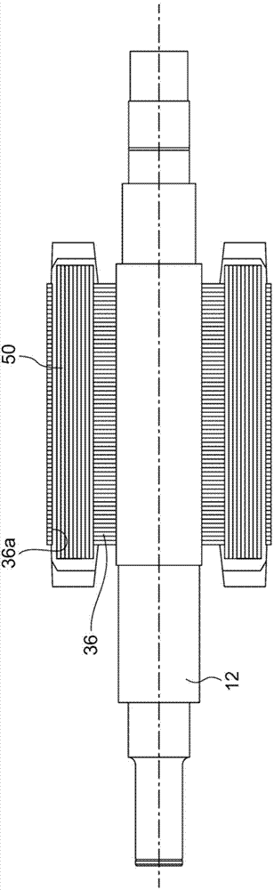
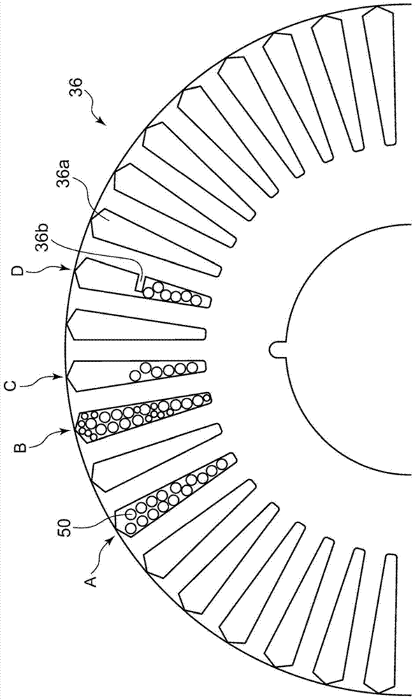
[0017] The rotor 36 is similarly formed by laminating a plurality of thin-plate-shaped electrical steel sheets that were punched out in the same circular shape. A circular hole for inserting the rotating shaft 12 toward the center is formed on the rotor 36, and a plurality of slots 36a of the same shape extending radially are formed at equal intervals on its outer peripheral side (refer to image 3 ). The circular bore of the rotor 36 is secured to the motor shaft 12 by an inter...


PUM


Abstract

The invention provides a squirrel-cage induction motor. Serving as a conductor in a slot, cost rise can be inhibited at the same of that copper is being used. The motor (10) has a rotor (36), which is composed of laminated steel sheets that are formed with slots (36a). A copper wire extending in a direction of lamination, is arranged in the slots.

Description

technical field [0001] This application claims priority based on Japanese Patent Application No. 2012-258721 filed on November 27, 2012. The entire content of the application is incorporated in this specification by reference. [0002] The present invention relates to the structure of a cage induction motor. Background technique [0003] Cage-type induction motors have a rotor with conductors cast in slots. The cage-type induction motor in which the rotor is made of die-cast aluminum embedded in slots is the mainstream (for example, Patent Document 1), but in recent years, in order to improve the efficiency of the motor, copper castings with higher conductivity than aluminum have been used. Cage-type induction motors that manufacture rotors are also put into practical use. [0004] Patent Document 1: Japanese Patent Laid-Open No. 2003-9483 [0005] However, copper has a higher melting point than aluminum, so die-casting is difficult, and conventional aluminum die-casting...

Claims


Application Information

Patent Timeline
IPC IPC(8): H02K1/22H02K1/28
CPCH02K17/16H02K15/0012H02K17/20
Inventor 水谷清信竹岛丰藤野泰充三成贵浩
Owner SUMITOMO HEAVY IND LTD
Why Eureka
Try Eureka