

U shaped riveted joint and riveting gun joint
A technology of riveting head and connecting head, applied in the field of connecting head, can solve the problems of springback and springback of riveting head, and achieve the effect of solving the springback
Inactive Publication Date: 2010-12-01
NORTHWESTERN POLYTECHNICAL UNIV +1
View PDF0 Cites 2 Cited by
- Summary
- Abstract
- Description
- Claims
- Application Information
AI Technical Summary
Problems solved by technology
In order to overcome the deficiencies of springback in prior art riveting, the present invention provides a joint between a U-shaped riveting head and a riveting gun. The U-shaped riveting head and the connecting head are connected by a transition fit. Move, can solve the springback problem of the riveting head
Method used
View moreImage
Smart ImageViewing Examples

Examples
Embodiment Construction
Login to View More PUM
 Abstract
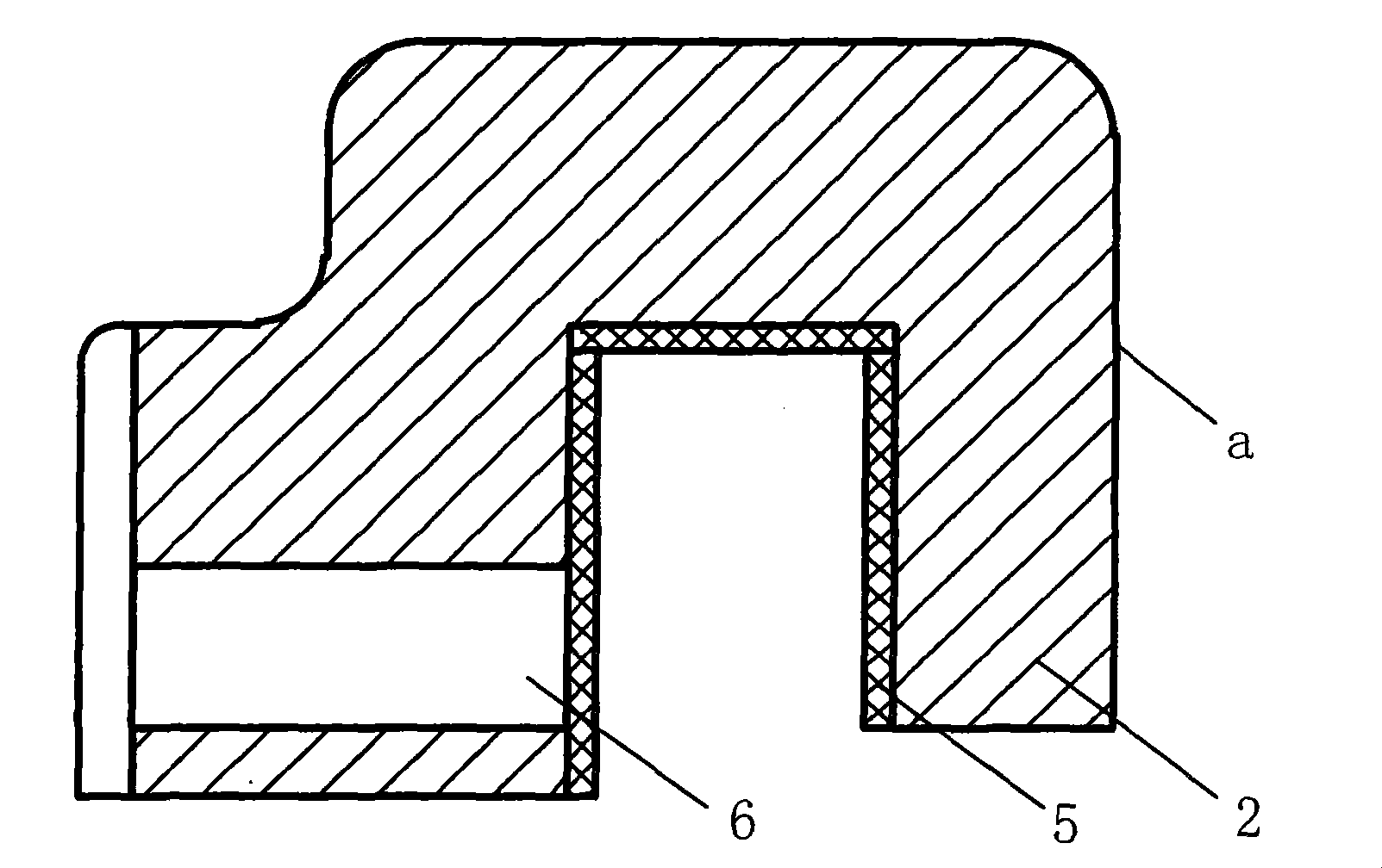
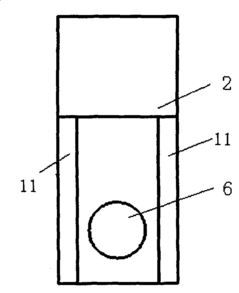
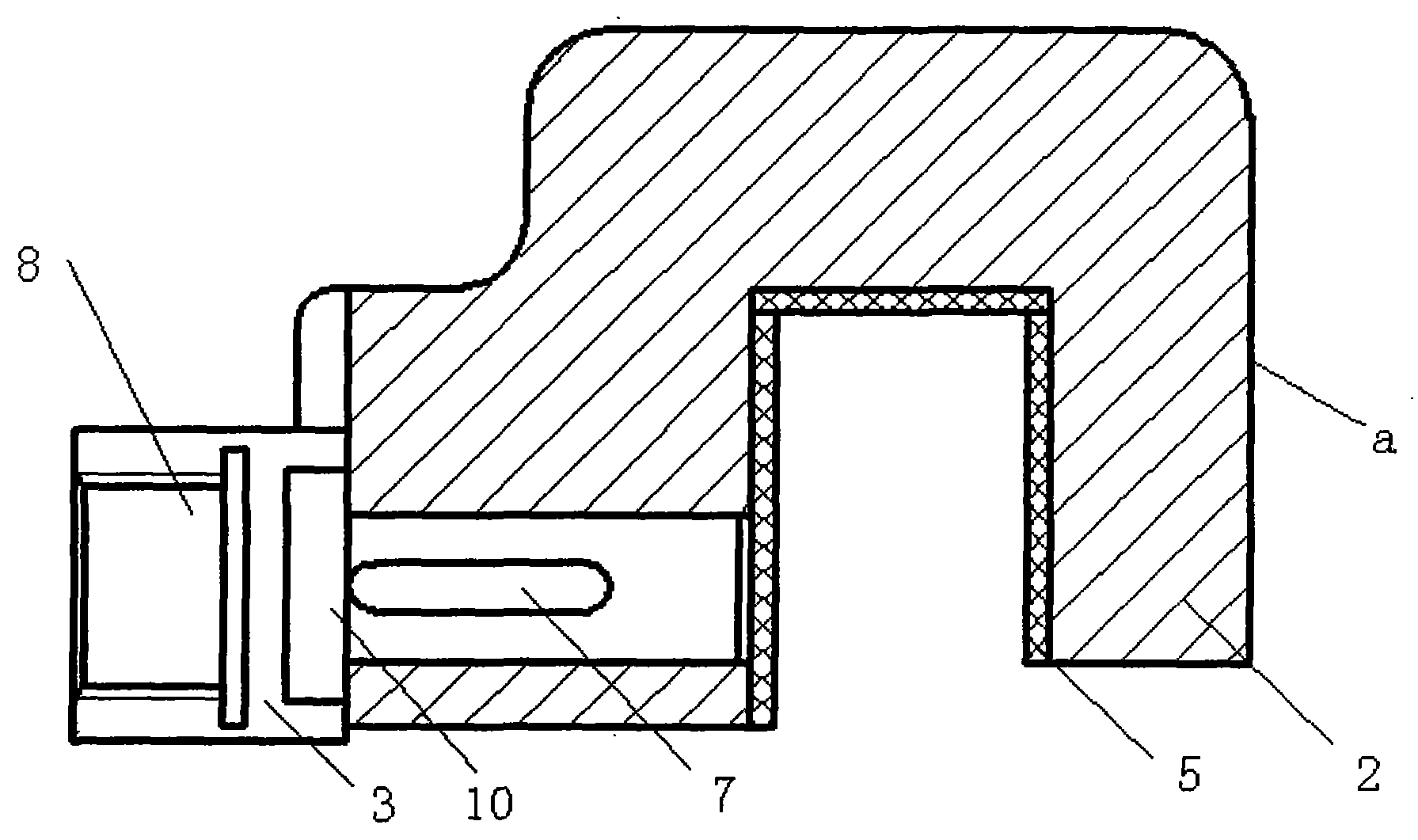
The invention discloses a U-shaped rivet joint, which is characterized in that the rivet joint takes a shape of an inverted U-shaped structure, a bayonet is arranged downwards, the lower end of the tail of the rivet joint is provided with a connecting hole, and the side wall which is axially opposite to the connecting hole is provided with a screwed hole. The invention also discloses a connector used for connecting the U-shaped rivet joint and a rivetter, which is characterized in that the connector takes a shape of a column-table structure, the head of the connector is a column which is provided with a key slot and in transition fit with the connecting hole on the U-shaped rivet joint in a transition way, the tail of the connector is a round table which has one concave station respectively at the left side and the right side which are matched with two bosses at the tail of the U-shaped rivet joint, and the radial center of the round table is provided with a screwed hole. As the bayonet of the U-shaped rivet joint can escape from the non-open part, the riveting of the non-open part can be realized; the U-shaped rivet joint and the connector adopt the transition fit connection, as the two can move relatively, the rebound problem of the rivet joint can be solved.
Description
Connecting head of U-shaped riveting head and riveting gun technical field The invention relates to a connecting head, in particular to a connecting head between a U-shaped riveting head and a riveting gun. Background technique Riveting is a very widely used connection method, especially in the aerospace field, where a large number of riveting processes are used in the product assembly process. The structure of aerospace products is complex, and the actual product has many parts with poor structure opening, and these parts often use riveting technology. Refer to Figure 7. The riveting head of the existing riveting gun is located at the head of the riveting gun. When riveting, the riveting head 1 is aligned with the rivet at the riveting position. For some complex structures, when using this riveting gun to work, the riveting head 1 cannot touch the rivet, so that the riveting cannot be performed. When encountering this situation, product design has to change riveting t...
Claims
Login to View More Application Information
Patent Timeline
 Patent Type & AuthorityPatents(China)
IPC IPC(8): B21J15/38
Inventor曹增强许旭东王浩一罗云何凤涛盛熙朱倩薛航
OwnerNORTHWESTERN POLYTECHNICAL UNIV