Forming method of flat pipe fitting

A forming method and technology of flat tubes, which are applied in the field of pipe fittings forming, can solve the problems of excessive grinding amount, reduced grinding amount, and low part qualification rate, etc., and achieve reduced grinding amount, reduced workload, and good forming effect Effect

Inactive Publication Date: 2020-07-03
SICHUAN FUTURE AEROSPACE IND LLC
View PDF7 Cites 0 Cited by
  • Summary
  • Abstract
  • Description
  • Claims
  • Application Information

AI Technical Summary

Problems solved by technology

[0004] The purpose of the present invention is to provide a method for forming flat pipe fittings in view of the problems of excessive grinding and low pass rate of parts in the forming process of flat pipe fittings in the prior art. This method uses a welding seam to connect the plates into The closed ring body greatly reduces the amount of grinding. The mold core is added inside the pipe fittings, and the inside and outside are formed at the same time, which solves the problem of part springback, reduces the workload of manual shape correction, makes the pipe fittings more effective, and improves production efficiency. It also strengthens the quality assurance of products and realizes the mass production of flat pipe fittings

Method used


Image

  • Forming method of flat pipe fitting
  • Forming method of flat pipe fitting
  • Forming method of flat pipe fitting

Examples


Embodiment 1

[0034] Pipe processing method of the present invention, its steps are as follows:

[0035] Step A:

[0036] Picking: pick up 1Cr18Ni9Ti plate or other plates;

[0037] Inspection 1: Check whether there are scratches and other defects on the surface of the material that are half of the negative difference of the thickness of the plate, check whether the batch number of the material is consistent and record it, the material standard is in accordance with GJB2505-95, the plate specification and grade and the plate thickness are 2±0.15mm;

[0038] Cutting: brush the surface of the sheet before cutting to protect it from splashing;

[0039] Inspection 2: Appearance inspection, there are no scratches, crushes, pits and other defects on the surface of the wool that exceed half of the negative difference of the board;

[0040] Fitter 1: Before bending the plate, first remove the splash and edge ablation layer on the surface of the plate, polish the surface defects of the wool, polis...

Embodiment 2

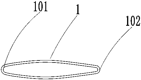
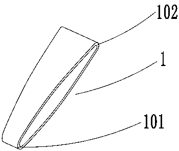
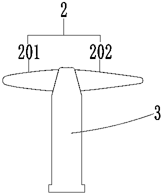
[0057] In this embodiment, the difference from Embodiment 1 is that the mold core in the step B adopts a left and right two-lobed structure, including a left mold core 201 and a right mold core 202, and the left mold core 201 and the right mold core 202 A supporting device 3 is arranged between them, and the supporting device 3 satisfies: it can apply force to the left mold core 201 and the right mold core 202 at the same time, so that the left mold core 201 fits the left inflection point 101 position of the inner wall of the pipe fitting, and the right mold core 202 Fit the right inflection point 202 position of the inner wall of the pipe fitting.

[0058] In this solution, during the radial forming process of the flat pipe fitting 1, the mold core 2 of the two-sided structure is used and the supporting device 3 is provided, so that the mold core 2 at the left inflection point 101 and the right inflection point 102 in the forming process fits more closely with the inner wall o...


PUM


Abstract

The invention relates to the technical field of pipe fitting forming, in particular to a forming method of a flat pipe fitting. The forming method comprises the following steps that A, edge rolling isconducted, wherein a plate is bent and rolled, the two ends of the plate are welded, and the plate forms a closed ring body through a welding seam; B, radial forming is conducted, wherein a mold corematched with the preset shape of the pipe fitting is added into the welded closed ring body, then the side wall of the pipe fitting is pressed to make the radial section of the pipe fitting achieve apreset shape, and the welding seam is made to avoid the inflection point position of the closed ring body on the radial section in the process; and C, axial forming is conducted, wherein after the radial section of the pipe fitting is formed, the front end and the rear end of the pipe fitting are cut correspondingly to make the pipe fitting achieve a preset shape in the axial direction. Accordingto the forming method, the plate is connected into the closed ring body through the welding seam, the grinding amount is greatly reduced, the mold core is added into the pipe fitting, the interior and the exterior of the pipe fitting are formed simultaneously, the problem of part springback is solved, the workload of manual shape correction is reduced, the pipe fitting forming effect is better, the quality guarantee of products is enhanced while the production efficiency is improved, and mass production of the flat pipe fitting is achieved.

Description

technical field [0001] The invention relates to the technical field of pipe fitting forming, in particular to a method for forming flat pipe fittings. Background technique [0002] There are many tubular parts in the parts of aviation and aerospace equipment, such as figure 1 and figure 2 As shown in FIG. 1 , it is a schematic structural view of a flat pipe fitting 1 , the cross section of which is a closed ring structure, and the left and right inflection points 101 and 102 are respectively arranged on both sides of the ring structure. [0003] For this type of flat pipe fittings, the traditional process can be roughly divided into two categories, one is to form the whole by multiple stretching, this method can ensure the size of the profile, but the wall thickness of the part will also be increased due to multiple stretching Excessive thinning; the other is the combination of welding and forming. Two half-pipes are formed from two sheets, and the two sides are respectiv...

Claims


Application Information

Patent Timeline
IPC IPC(8): B23P15/00
CPCB23P15/00
Inventor 周超方园凃鹏
Owner SICHUAN FUTURE AEROSPACE IND LLC
Why Eureka
Try Eureka