Sand screening equipment for house construction

A kind of screening equipment and construction technology, which is applied in the direction of screening, application, solid separation, etc., can solve the problem of inconvenient sand classification and screening, and achieve the effect of reducing settings, increasing grinding force, and simplifying the structure

Inactive Publication Date: 2021-02-19
台州和源建设有限公司
View PDF11 Cites 1 Cited by
  • Summary
  • Abstract
  • Description
  • Claims
  • Application Information

AI Technical Summary

Problems solved by technology

[0004] Aiming at the deficiencies in the prior art, the present invention provides sand screening equipment for building construction, to solve the current problem that it is not convenient to classify and screen sand

Method used


Image

  • Sand screening equipment for house construction
  • Sand screening equipment for house construction

Examples


Embodiment 1

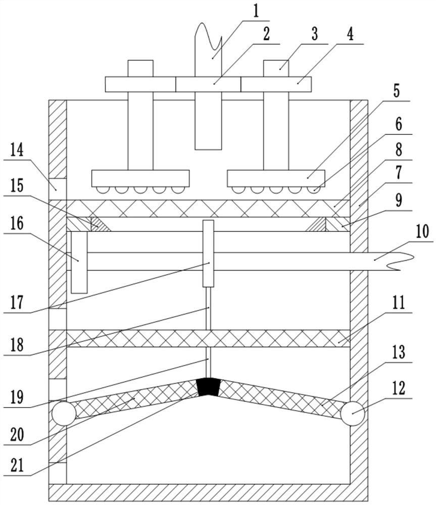
[0026] Such as figure 1 As shown, the sand screening equipment for house construction includes a frame, on which a screening box 7 is fixed, and the upper end of the screening box 7 is opened to form a sand feeding port. The hopper is used to drop the sand into the screening box 7 through the feed hopper.

[0027] The screening box 7 is provided with a rotating sieve 8, a sliding sieve 11 and a oscillating sieve in sequence from top to bottom, and the sieve apertures of the rotating sieve 8, sliding sieve 11 and oscillating sieve are successively reduced to achieve the purpose of grading and screening the sand layer by layer. . The side wall of the screening box 7 is provided with four outlets 14 respectively located at the bottom of the screening box 7, above the rotating screen 8, above the sliding screen 11, and above the swinging screen. A valve is installed in the outlet 14, and the outlets 14 are all connected There is a discharge pipe (not shown in the figure), and du...

Embodiment 2

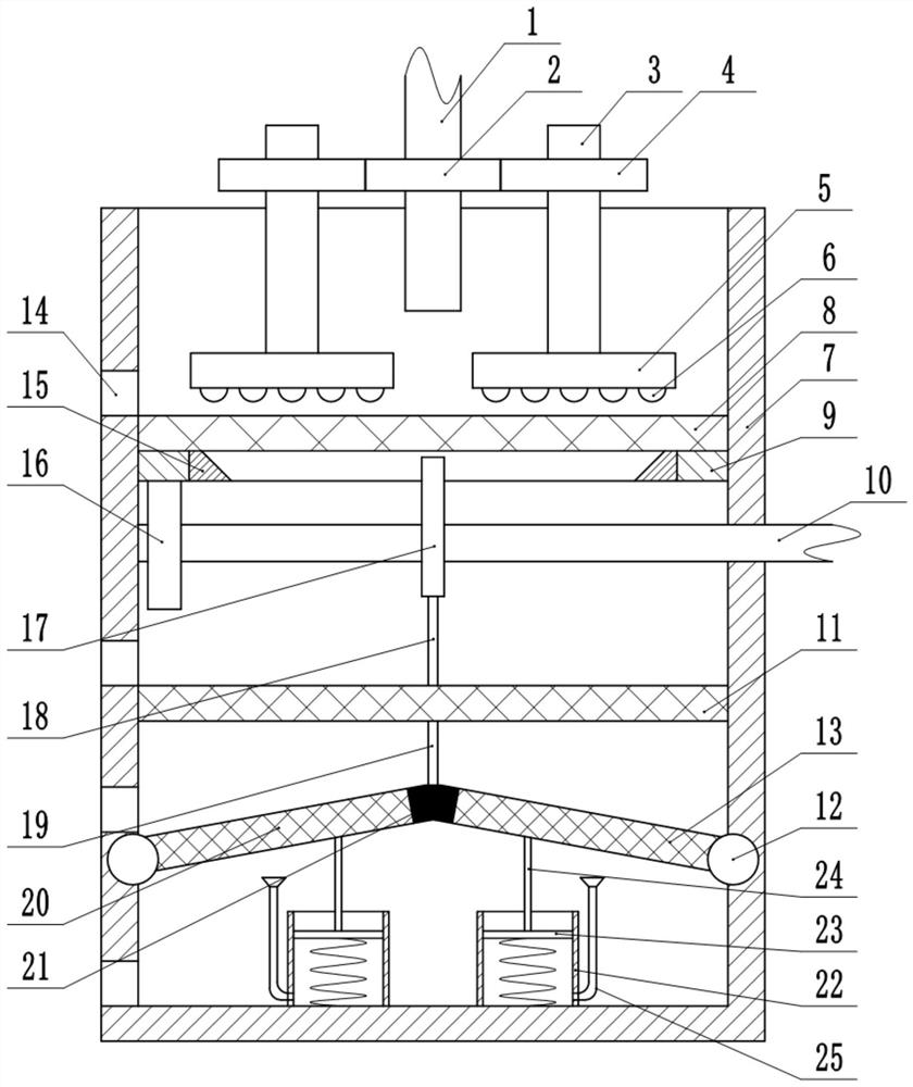
[0036] The only difference between this embodiment and embodiment 1 is: the combination figure 2 As shown, the first spring installed between the lower end of the opposite side of the first half sieve 13, the second half sieve 20, and the bottom of the screening box 7 is replaced by a piston barrel 22. Specifically, the piston barrel 22 is vertically slidably connected There is a piston 23, the upper end of the piston 23 is fixed with a piston rod 24, the upper end of the piston rod 24 is offset against the first half sieve 13 or the second half sieve 20, a second spring is fixed between the lower end of the piston 23 and the bottom of the piston barrel 22, and the piston barrel 22 Bottom is communicated with ventilator 25, and ventilator 25 openings face up and communicate with expanding mouthpiece, and filter cloth is fixed in the expanding mouthpiece, prevents sand from falling in the ventilator 25 by filter cloth.

[0037] In this embodiment, the first half sieve 13 and t...


PUM


Abstract

The invention belongs to the field of house construction, in particular to sand screening equipment for house construction. The sand screening equipment comprises a machine frame, wherein a screeningbox is fixed to the machine frame; the upper end of the screening box is opened; a rotating sieve, a sliding sieve and a swinging sieve are sequentially arranged in the screening box from top to bottom; the pore sizes of sieve holes of the rotating sieve, the sliding sieve and the swinging sieve are sequentially reduced; the rotating sieve is rotatably connected to the inner wall of the screeningbox; a plurality of grinding shafts are rotatably connected to the machine frame, and grinding discs are fixed to the lower ends of the grinding shafts; the sliding sieve is vertically connected to the inner wall of the screening box in a sliding manner, and a first connecting rod is fixed to the upper end of the sliding sieve; the swinging sieve comprises a first half sieve and a second half sieve, and the first half sieve and the second half sieve are separately hinged to the opposite two sides of the inner wall of the screening box, and an elastic band is fixedly connected between the opposite ends of the first half sieve and the second half sieve; and a second connecting rod is fixed between the elastic band and the sliding sieve. By adopting the scheme, the problem that graded screening on sand is inconveniently performed can be solved.

Description

technical field [0001] The invention belongs to the field of house construction, and in particular relates to sand screening equipment for house construction. Background technique [0002] Screening is the process of using a sieve to make the fine-grained materials smaller than the sieve holes pass through the sieve surface, while the coarse-grained materials larger than the sieve holes stay on the sieve surface, thereby completing the process of separating coarse and fine materials. Sand is a must in construction engineering. One of the few materials, a large amount of sand screening is often required in housing construction projects to remove large particles of sand and some impurities in the sand, so that the purity of the material can be improved, and the quality of construction projects can be increased. Construction projects are usually carried out on sand When sifting sand, sand screening devices are used. [0003] The sand particles in the sand are also divided into...

Claims


Application Information

Patent Timeline
Patent Type & Authority Applications(China)
IPC IPC(8): B02C7/11B02C23/14B07B1/08B07B1/28B02C23/18
CPCB02C7/11B02C23/14B07B1/08B07B1/28B02C23/18
Inventor 王文伟梁萧
Owner 台州和源建设有限公司
Why Eureka
Try Eureka