Wireless sensing type rectifying system of rail gantry crane

A technology of wireless sensing nodes and gantry cranes, which is applied in the direction of walking bridge cranes, load suspension components, safety devices, etc., can solve the problems of transmission ratio changes, position signal accuracy decline, large errors, etc., and achieve high deviation correction accuracy , the effect of easy installation

A technology of wireless sensing nodes and gantry cranes, which is applied in the direction of walking bridge cranes, load suspension components, safety devices, etc., can solve the problems of transmission ratio changes, position signal accuracy decline, large errors, etc., and achieve high deviation correction accuracy , the effect of easy installation

CN101417773AInactive Publication Date: 2009-04-29CHANGZHOU GT ELECTRIC

Image

  • Wireless sensing type rectifying system of rail gantry crane

Examples


Embodiment Construction

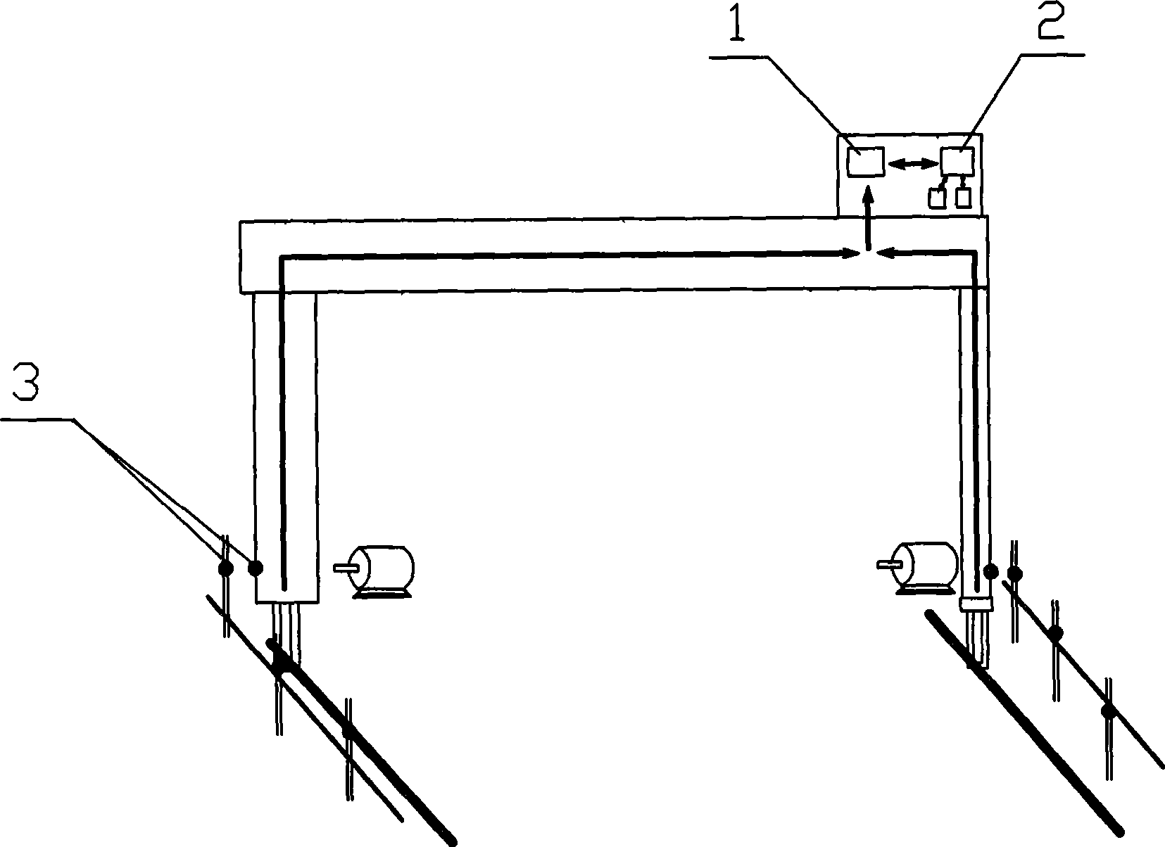
[0011] like figure 1 As shown in the figure, a wireless sensor type deviation correction system for a rail gantry crane, which has a deviation correction processor 1 and a programmable logic controller 2 installed in the electrical room of the gantry crane, and also has rigid legs, flexible legs and rail guardrails respectively arranged on the gantry crane. The sensor nodes 3 on the sensor node 3 for collecting signals, each sensor node 3 is in the same wireless sensor network.

[0012] The wireless sensing nodes 3 on the rail guardrail of the gantry crane are arranged at intervals by the guardrails, one for each railing, and the distance between two adjacent railings is 20-30m.

[0013] By installing wireless sensor nodes 3 on the rigid legs, flexible legs and rail barriers of the gantry crane, and using the self-positioning function of the wireless sensor network nodes, the positions of the rigid legs and flexible legs on the track of the gantry crane can be directly measure...


PUM


Abstract

The invention relates to a wireless sensing type rectifying system of rail gantry cranes, which is provided with a rectifying processor arranged in a gantry crane electric chamber and a programmable logic controller, and wireless sensor nodes which are respectively arranged at a rigid leg and a flexible leg of the gantry crane and a rail guardrail and for collecting signals. By using the self-positioning function of the wireless sensor nodes, the positions of the rigid leg and the flexible leg on the rail can be directly detected when the gantry crane is in walking, and the position data is transmitted to the rectifying processor, and the precision goal speeds of the rigid leg and the flexible leg can be obtained by appropriate PID algorithm, and a speed value is transmitted to the programmable logic controller and used as an order value of a driving device or an inverter to control the rotation speeds of the rigid leg and the flexible leg cargo motors, thus realizing the automatic rectification of the gantry crane when in walking.

Description


Claims


Application Information

Patent Timeline
29 Apr 2009
Publication
CN101417773A