Light source assembly

A technology of light source components and light sources, applied in the directions of light sources, optical elements, point light sources, etc., can solve the problems of reduced light output rate, reduced light transmittance, and affected light field distribution of light-emitting diodes

Inactive Publication Date: 2009-04-29
FOXSEMICON INTEGRATED TECHNOLOGY (SHANGHAI) INC +1
View PDF0 Cites 18 Cited by
  • Summary
  • Abstract
  • Description
  • Claims
  • Application Information

AI Technical Summary

Problems solved by technology

Since the packaging shell and the lens of the light-emitting diode are usually composed of solid materials with a refractive index much higher than that of air, the gap between the light-emitting diode and the lens will cause the following problems: First, light is prone to occur when it exits the light-emitting diode The phenomenon of total reflection reduces the light emitting rate of the light-emitting diode; second, the light has strong reflection and refraction at the two interfaces of the surface of the light-emitting diode and the surface of the lens, and the reflection of light will cause waste of light and reduce the light transmittance , while refraction affects the distribution of the light field
[0004] If the light source and the light processing element are made into direct contact, the above problems can be solved theoretically. However, since the shell of the light emitting diode and the light processing element are all solid materials, the tiny gap between the contact surfaces will cause unpredictable The phenomenon of light interference makes it more difficult to control the light field

Method used


Image

  • Light source assembly
  • Light source assembly
  • Light source assembly

Examples


Embodiment Construction

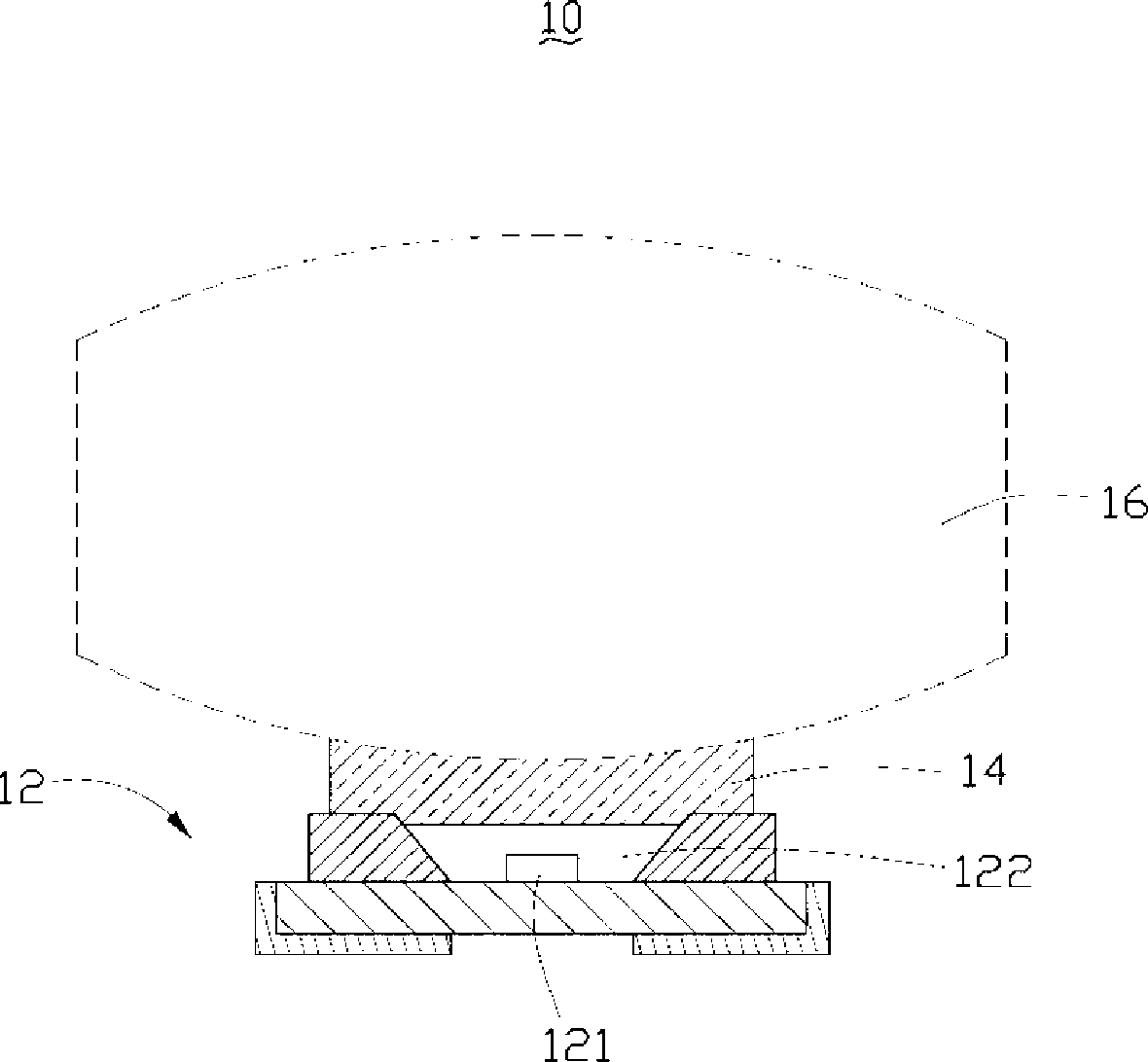
[0013] refer to figure 1 , the light source assembly 10 of the first embodiment includes a light source 12 , a light-transmitting filling layer 14 and a light processing element 16 . The light source 12 includes a light emitting portion 121 and a light emitting portion 122 . The light-transmitting filling layer 14 fills the gap between the light-exiting portion 122 and the light-processing element 16 , and the light-transmitting filling layer 14 makes the light-exiting portion 122 and the light-processing element 16 bond.

[0014] The light emitting unit 121 can be a light emitting diode or a diode laser, and of course other solid light sources are also applicable. The light emitting part 122 is the encapsulation shell of the light emitting part 121, and is usually made of a material with high transparency, such as glass, silica gel, transparent silicone rubber or transparent resin such as epoxy resin, polymethacrylic resin, and the like.

[0015] The light-transmitting fill...


PUM


Abstract

The invention relates to a light source module, which comprises at least one light source and at least one light processing element, wherein the light source comprises a light emergent part; and the light source module further comprises a transmission packing layer which fills a gap between the light emergent part and the light processing element. The light source module can reduce reflection and improve refraction when light enters the light processing element, so as to improve light utilization rate.

Description

technical field [0001] The invention relates to a light source assembly. Background technique [0002] At present, light-emitting diodes have been widely used in various fields. In practical applications, special light processing components are usually used to process the light emitted by light-emitting diodes to meet various practical needs. For example, often in the light-emitting part of light-emitting diodes Set the lens to focus the light. [0003] In this design, the light first exits from the inside of the LED to the outside of the LED, passes through the gap between the lens and the LED, and then enters the lens. Since the packaging shell and the lens of the light-emitting diode are usually composed of solid materials with a refractive index much higher than that of air, the gap between the light-emitting diode and the lens will cause the following problems: First, light is prone to occur when it exits the light-emitting diode The phenomenon of total reflection red...

Claims


Application Information

Patent Timeline
Patent Type & Authority Applications(China)
IPC IPC(8): F21V5/00F21V9/08F21V19/00H01L33/00F21Y101/02
CPCG02B19/0061H01L33/58F21K9/00G02B19/0028G02B27/0916G02B17/0864G02B19/0052F21Y2101/02F21Y2115/10F21K9/68
Inventor 徐智鹏李泽安
Owner FOXSEMICON INTEGRATED TECHNOLOGY (SHANGHAI) INC
Why Eureka
Try Eureka