Stretchable fabric

A fabric and warp technology, applied in the direction of fabrics, multi-strand fabrics, textiles, etc., can solve the problems of rising manufacturing costs and complex manufacturing

Inactive Publication Date: 2009-04-29
ITG AUTOMOTIVE SAFETY TEXTILES GMBH
View PDF0 Cites 5 Cited by
  • Summary
  • Abstract
  • Description
  • Claims
  • Application Information

AI Technical Summary

Problems solved by technology

Although this does result in an almost optimal fabric in terms of air permeability, the manufacturing costs of such fabrics therefore rise significantly, the additional steps in the production of "coating or lamination" complicate the entire production and thus naturally become very important

Method used


Image

  • Stretchable fabric
  • Stretchable fabric
  • Stretchable fabric

Examples


Embodiment Construction

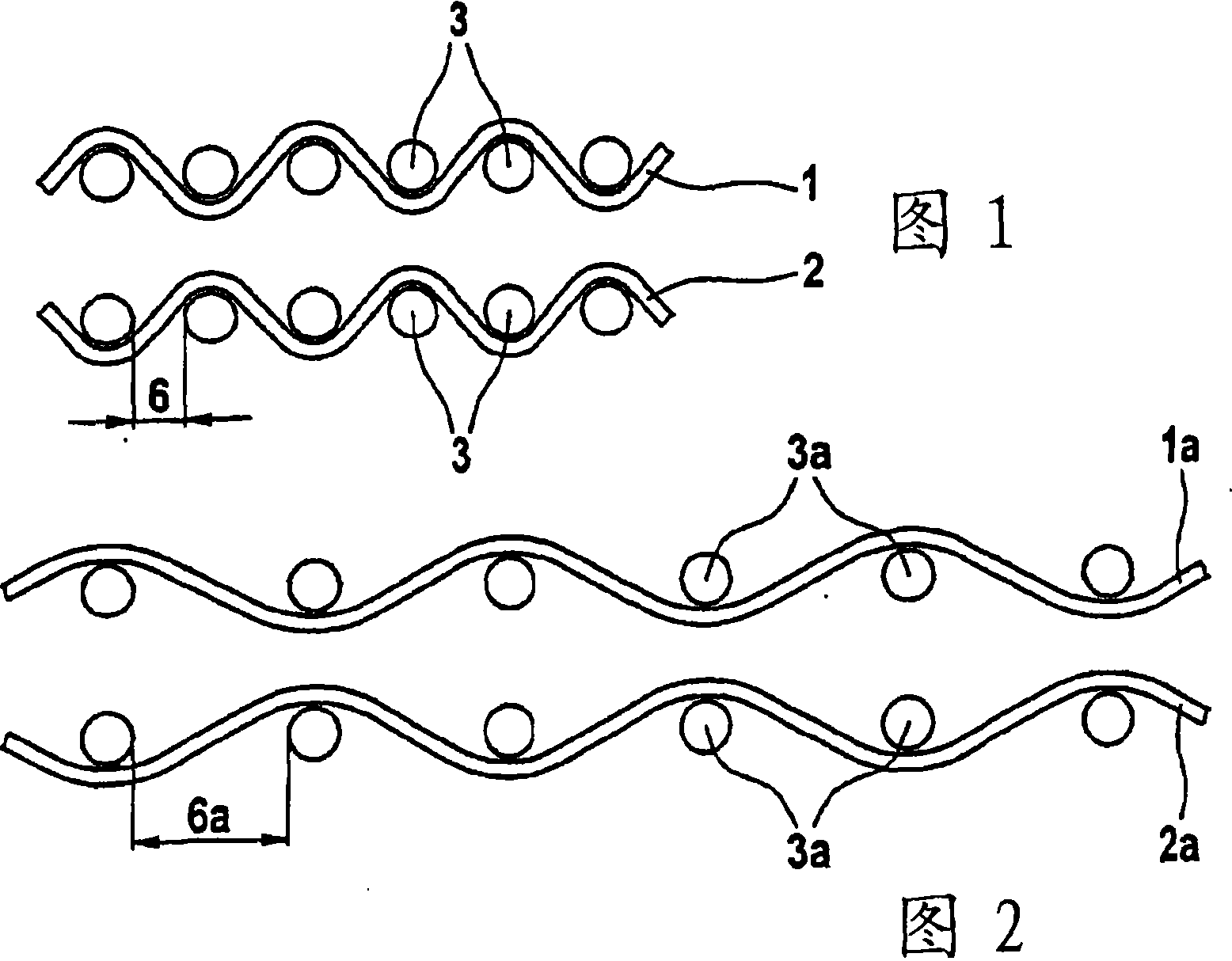
[0018] Referring now to FIG. 1, there is shown in a greatly enlarged circle a weft yarn 3 interwoven by warp yarns 1 and 2 in a fabric woven in a conventional L1 / 1 plain weave, where two weft The spacing between the yarns is indicated with reference numeral 6 . FIG. 1 top view shows a fabric section along a first warp thread 1 surrounding a weft thread 3 .

[0019] The next view shows a plain weave fabric section as known from the prior art along the second warp thread 2 . The spacing 6 between weft threads 3 (between warp threads, the same response) is defined by the structure.

[0020] Reference is now made to Figure 2 which shows a cross-section of the fabric shown in Figure 1 but in a stretched state, that is to say for example as the fabric is applied in an inflated or inflated airbag. Injecting an airbag (not shown) with gas generated by an inflator (not shown) and / or cushioning the impact of the vehicle occupant results in a tensile loading of the fabric so that the s...


PUM


Abstract

Disclosed is a fabric comprising first and second warp threads and first and second weft threads. Said fabric is characterized in that the first warp threads (11, 12) and the first weft threads (13) form a basic fabric (17) while the second warp threads (14), along with the second weft threads (15), form a covering fabric that adjoins the basic fabric (17), the second warp threads (14) also being interwoven with the first weft threads (13).

Description

technical field [0001] The present invention relates to a stretchable fabric comprising first and second warp yarns and first and second weft yarns. Background technique [0002] Fabrics are known for producing airbags for passenger restraint systems in motor vehicles, which fabrics are bonded in an uncoated manner. In application, an airbag made of such a fabric would be rapidly inflated by gas injected into it, the resulting pressure would subject the airbag to a stretching tension, causing the fabric structure to open (i.e., open by stretching its structure). increase the breathability of the fabric), allowing inflation gases to escape. This can greatly hinder the response of the airbag, for example because the airbag deploys slowly and thus loses gas continuously. Therefore, the airbag delays the formation of its cushioning effect to protect the occupant, and there may also be a danger of injury due to the overflow of inflation gas. [0003] Attempts have been made to...

Claims


Application Information

Patent Timeline
Patent Type & Authority Applications(China)
IPC IPC(8): D03D1/02D03D11/00D03D15/08D03D15/56D03D15/567
CPCD03D11/00B60R21/235B60R2021/23509D03D15/08D03D1/02D03D15/56
Inventor 约尔格·鲁舒尔特
Owner ITG AUTOMOTIVE SAFETY TEXTILES GMBH
Why Eureka
Try Eureka