Hydraulically actuable vehicle brake having a locking means

A vehicle braking and locking device technology, which is applied in the direction of brake actuators, gear transmission mechanisms, mechanical equipment, etc., can solve complex and huge problems, and achieve the effects of shortening time and reducing manufacturing costs

Inactive Publication Date: 2009-04-29
LUCAS AUTOMOTIVE GMBH
View PDF3 Cites 11 Cited by
  • Summary
  • Abstract
  • Description
  • Claims
  • Application Information

AI Technical Summary

Problems solved by technology

However, this requires a relatively complex and bulky mechanism and correspondingly powerful electric components

Method used


Image

  • Hydraulically actuable vehicle brake having a locking means
  • Hydraulically actuable vehicle brake having a locking means
  • Hydraulically actuable vehicle brake having a locking means

Examples


Embodiment Construction

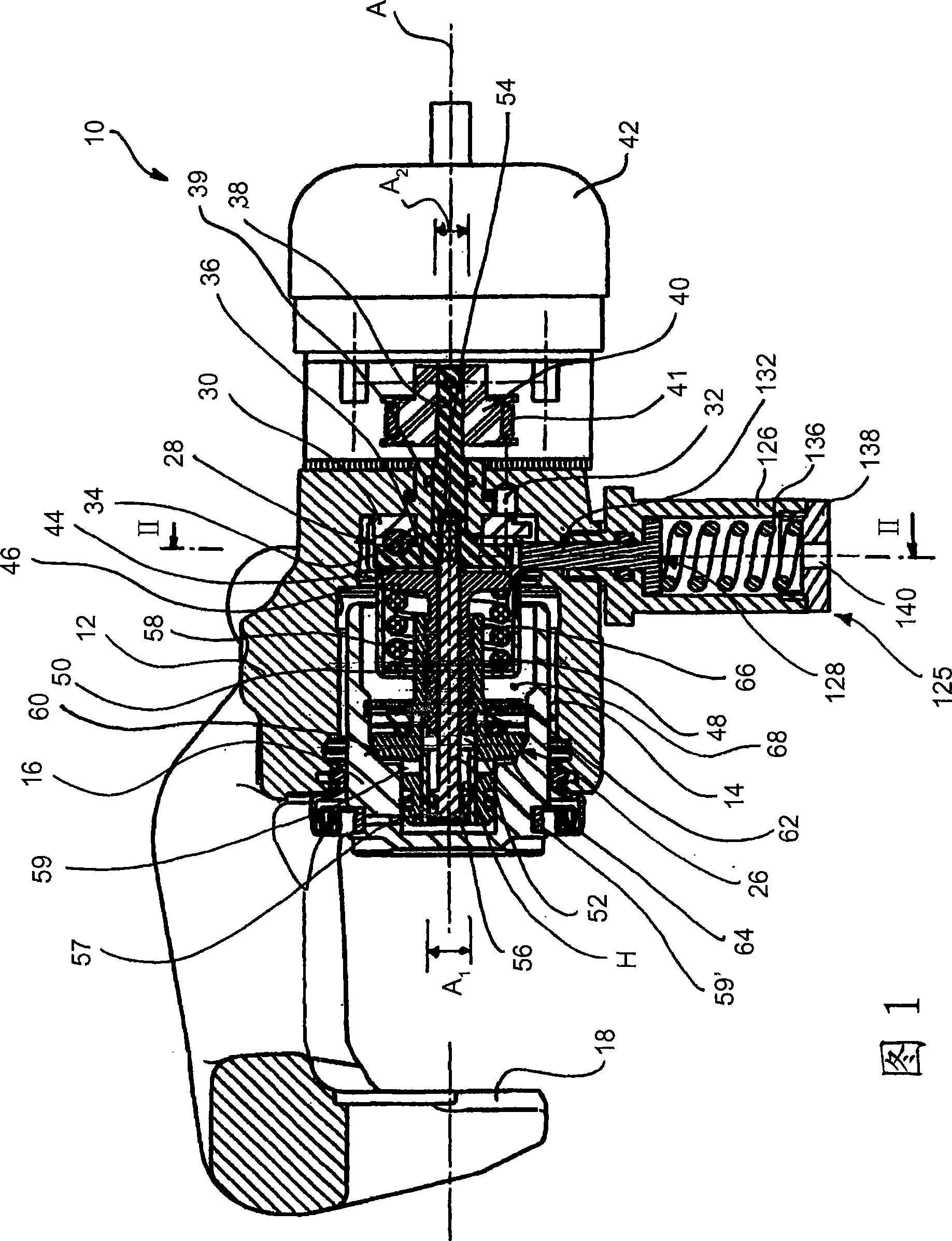
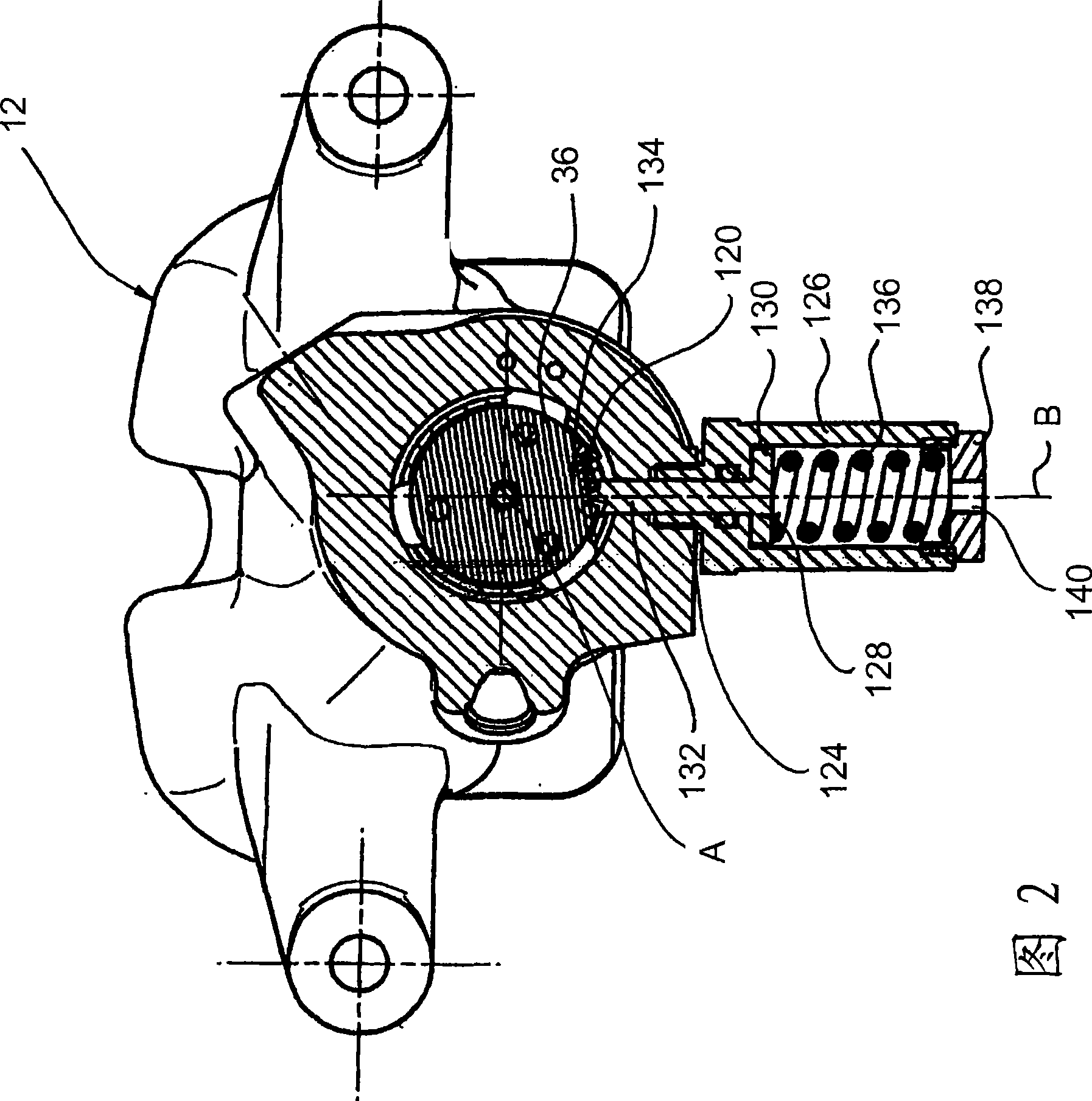
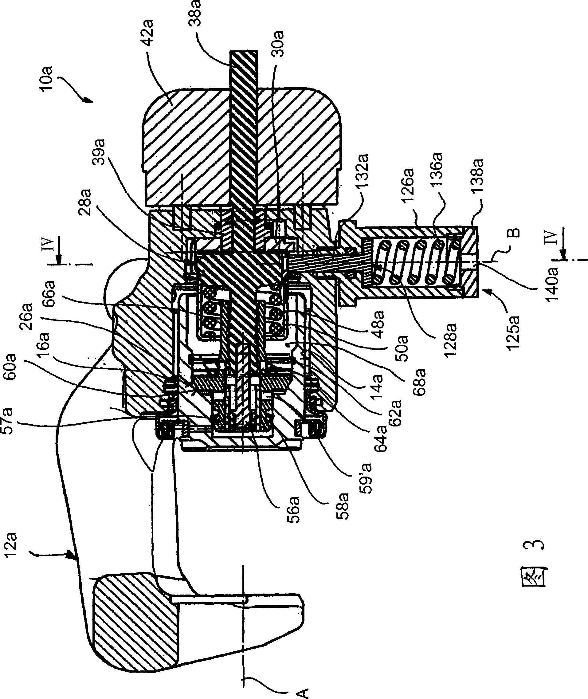
[0032] First, a first embodiment will be described below based on FIGS. 1 and 2 .

[0033] In FIG. 1 , a vehicle brake according to the invention is generally indicated by reference numeral 10 . It is designed with a housing 12 having a cylindrical opening 14 . A brake piston 16 is displaceably accommodated in the cylindrical opening 14 in a liquid-tight manner. The brake piston 16 can be mechanically connected at its end (left side in FIG. 1 ) to a brake pad carrier (not shown), to which the brake pad can be fixed. Opposite this brake pad there is a further brake pad which is fixed to the opposite housing part 18 . These brake pads are mounted in the housing 12 in a conventional manner according to the floating caliper principle.

[0034] The vehicle brake 10 also comprises blocking means 26 by which the brake piston 16 can be blocked in various axial positions along the longitudinal axis A of the piston. The blocking device 26 comprises in a first embodiment a ramp devic...


PUM


Abstract

The present invention relates to a vehicle brake (10) having a housing (12), a brake piston (16) which is accommodated in the housing (12) and is coupled to a brake lining (20), a blocking device (26) for locking the brake piston (16) within the housing (12), and an electromechanical actuating device (42) for actuating the blocking device (26) in a parking brake situation, wherein the brake piston (16), together with the housing (12), delimits a fluid chamber (68) which can be loaded with hydraulic fluid, with the result that the brake piston (16) can be displaced hydraulically within the housing (12) along a piston longitudinal axis (A) for actuating the vehicle brake (10).; There is provision in a vehicle brake of this type for the blocking device (26) to be assigned a locking arrangement (125) which acts mechanically on a component (36) of the blocking device (26) in a parking brake situation and blocks a restoring movement of said component (36).

Description

technical field [0001] The present invention relates to a hydraulically actuatable vehicle brake comprising a housing, a brake piston accommodated in the housing and coupled to a brake pad, a blocking device for retaining the brake piston within the housing, and a brake piston in the parking brake state An electromechanical actuation device of a lower activation blocking device, wherein the brake piston together with the housing defines a fluid chamber fillable with hydraulic fluid such that the brake piston actuating the vehicle brake is hydraulically movable within the housing along the piston longitudinal axis. Background technique [0002] Such vehicle brakes are known. Such a vehicle brake is thus known, for example, from the genre-defining document DE 10 2004 040 261 A1. With this vehicle brake, the brake disc is braked in the service braking state by filling the fluid chamber with hydraulic fluid, causing the brake piston to move within the housing and the brake pads...

Claims


Application Information

Patent Timeline
Patent Type & Authority Applications(China)
IPC IPC(8): F16D65/14
CPCF16D2129/02F16D2125/44F16D2125/36F16D2121/02F16D2127/06F16D2129/10F16D65/18
Inventor 库尔特·莫尔曼努埃尔·舒密芝
Owner LUCAS AUTOMOTIVE GMBH
Why Eureka
Try Eureka