
Improved ultra-high pressure stopped foot pedal control valve

A control valve, ultra-high pressure technology, applied in the direction of valve details, valve devices, functional valve types, etc., can solve the problems of small application range, inadequate sealing, waste of water resources, etc., to achieve wide application range, good sealing performance, and energy saving The effect of water resources

Inactive Publication Date: 2009-05-06
无锡威顺煤矿机械有限公司
View PDF0 Cites 3 Cited by
  • Summary
  • Abstract
  • Description
  • Claims
  • Application Information

AI Technical Summary

Problems solved by technology

[0002] The existing pedal control valve is not well sealed, and it takes a lot of effort to step on it, and due to the pressure of the liquid itself, the liquid will still flow out when the pedal is not stepped on, so water resources are wasted, and it is not suitable for work with a clean environment environment, the scope of application is small

Method used


Image

  • Improved ultra-high pressure stopped foot pedal control valve
  • Improved ultra-high pressure stopped foot pedal control valve
  • Improved ultra-high pressure stopped foot pedal control valve

Examples


Embodiment Construction

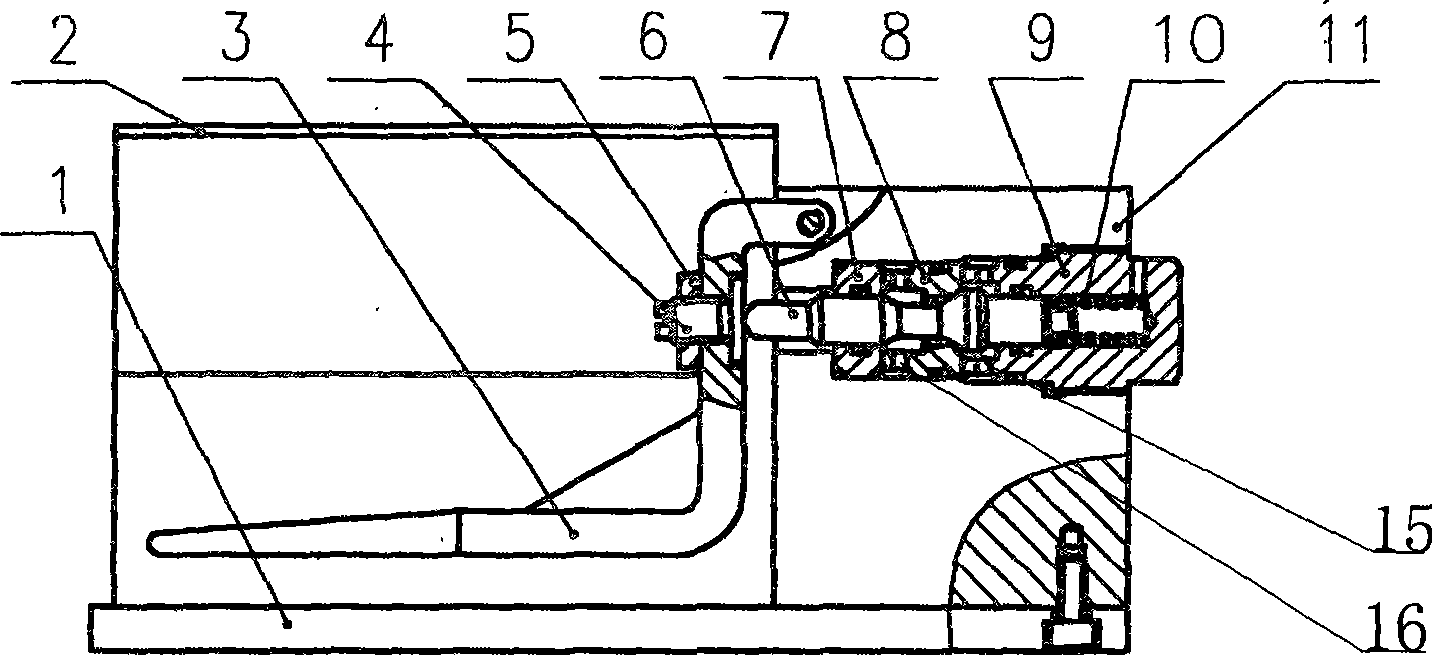
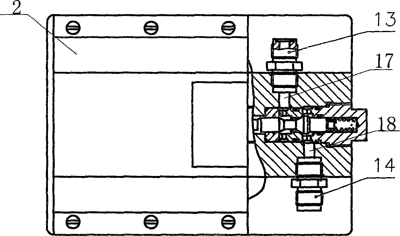
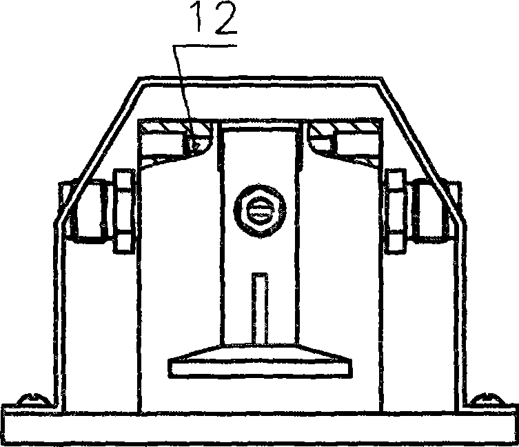
[0010] See figure 1 , figure 2 , image 3 , the present invention includes a bottom plate 1, a shield 2, a pedal 3, a valve body 6, a liquid outlet 13, and a liquid inlet 14. A valve body 11 is installed on the front of the bottom plate 1, and the pedal 3 is installed on the valve body through two cylindrical pins 12. 11. The pedal 3 is covered with a shield 2, the shield 2 is installed on the bottom plate 1, the valve core 6 is installed inside the valve body 11, the pedal 3 is directly facing the valve core 6, and an adjustment device is installed at the end of the valve body 11. The guide sleeve 7 and the valve seat 8 are installed in turn, the guide sleeve 7 is set on the valve core 6, the valve seat 8 is pressed and fixed on the valve body 11 by the screw sleeve 9, and a spring is pressed between the other end of the valve core 6 and the screw sleeve 9 10. The valve body 11 has a liquid inlet channel 18 and a liquid outlet channel 17. The valve seat 8 has a water outle...


PUM


Abstract

The invention provides an improved ultrahigh pressure cutoff foot control valve, which is well sealed, saves labor in treading, saves water resources because water returns back to a water tank through a water return hole when a treadle is loosened, and has a wide use range. The improved ultrahigh pressure cutoff foot control valve comprises a bottom plate, a protecting hood, the treadle, a valve body, a liquid outlet and a liquid inlet, wherein the front of the bottom plate is provided with the valve body; the treadle is arranged on the valve body through two cylindrical pins; the protecting hood covers the outside of the treadle and is arranged on the bottom plate; and a valve core is arranged inside the valve body. The improved ultrahigh pressure cutoff foot control valve is characterized in that one end of the treadle facing to the valve core is provided with a controlling device; an inner cavity of the valve body is provided with a guide sleeve and a valve seat in turn; the valve core is sleeved on the inner walls of the guide sleeve and the valve seat; the valve seat is compressed and fixed on the valve body by a threaded sleeve; and a spring on the other end of the valve core is connected with the inner wall of the threaded sleeve.

Description

(1) Technical field [0001] The invention relates to the field of pedal control valves, in particular to an improved ultra-high pressure cut-off pedal control valve. (2) Background technology [0002] The existing pedal control valve is not well sealed, and it takes a lot of effort to step on it, and due to the pressure of the liquid itself, the liquid will still flow out when the pedal is not stepped on, so water resources are wasted, and it is not suitable for work with a clean environment environment, the scope of application is small. (3) Contents of the invention [0003] In view of the above problems, the present invention provides an improved ultra-high pressure cut-off pedal control valve with good sealing. Stepping down saves effort, and when the pedal is released, the water returns to the water tank from the return hole, saving water resources and having a wide range of applications. [0004] Its technical scheme is as follows: it includes a base plate, a shield...

Claims


Application Information

Patent Timeline
Patent Type & Authority Applications(China)
IPC IPC(8): F16K31/62F16K21/04
Inventor 华钟麟
Owner 无锡威顺煤矿机械有限公司
Learn More