Bone anchors and methods of forming the same

A technology that demonstrates bone anchoring, applied in internal bone synthesis, medical science, surgery, etc., can solve the problems of increasing manufacturing and assembly costs

Inactive Publication Date: 2009-05-06
WARSAW ORTHOPEDIC INC
View PDF7 Cites 17 Cited by
  • Summary
  • Abstract
  • Description
  • Claims
  • Application Information

AI Technical Summary

Problems solved by technology

However, bone anchors assembled from multiple pieces or components often result in increased manufacturing and assembly costs

Method used


Image

  • Bone anchors and methods of forming the same
  • Bone anchors and methods of forming the same
  • Bone anchors and methods of forming the same

Examples


Embodiment Construction

[0027] DETAILED DESCRIPTION OF THE PREFERRED EMBODIMENT

[0028] For the purpose of promoting an understanding of the principles of the disclosure, reference will now be made to the embodiments illustrated in the drawings, and specific language will be used to describe the same. It is to be understood, however, that the scope of the invention is not intended to be limited thereby; any variations of the illustrated devices and further such improvements, and / or further applications of the inventive principles described and described herein, are justified as to Generally speaking, it is conceivable for those of ordinary skill in the art to which the present invention pertains.

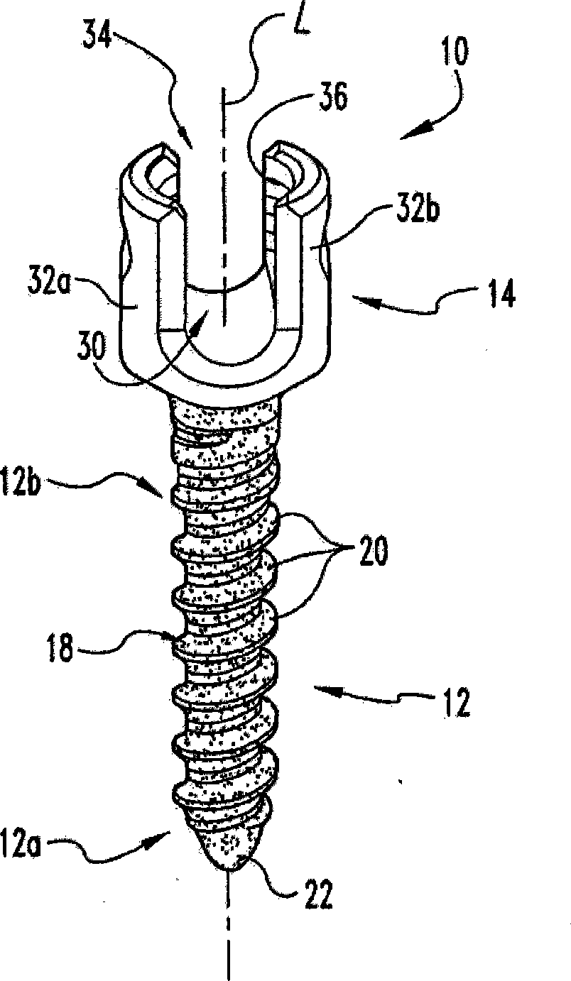
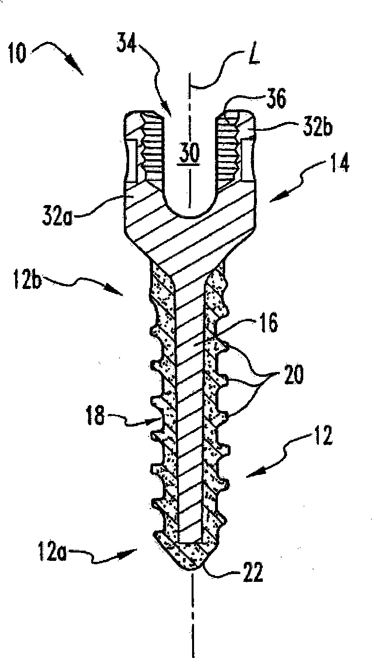
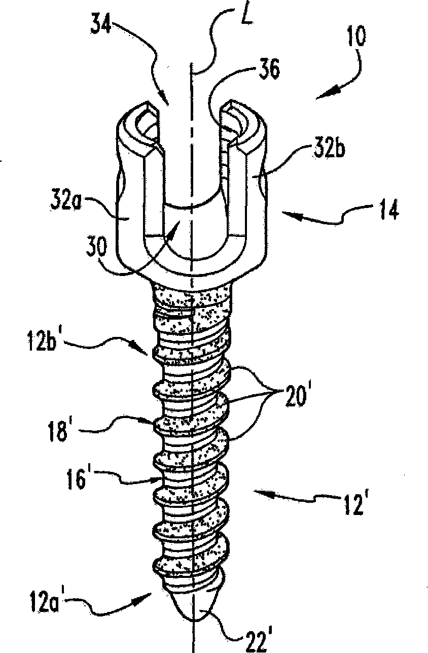
[0029] refer to figure 1 and 2 , which shows a form of bone anchor 10 according to the present invention. Bone anchor 10 extends along longitudinal axis L and generally includes a bone engaging portion 12 configured for engaging in or onto bone, and a graft engaging portion 14 configured for engaging a...


PUM


Abstract

A bone anchor (.10) including a bone engaging element (.12) and an implant engaging element (14). The bone engaging element (32) includes a first portion (.16) formed of a first material and a second portion (18) formed of a second material and extending at least partially along a length of the first portion (16), and with the second portion (1 S) of the bone engaging element ( 12) positioned between the first portion (16) and adjacent bone tissue when the bone engaging element (12) is engaged with the bone to provide an interface with the adjacent bone tissue. In one embodiment; the first portion (16) of the bone engaging element (12) exhibits a first level of rigidity and the second portion (18) exhibits a second level of rigidity less than the .first level of rigidily. In another embodiment, the bone engaging element (12) includes external threads (20), with the second portion (18) of the bone engaging element (12) defining at least a portion of the external threads (20).

Description

field of invention [0001] The present invention relates generally to the field of bone anchors, and more particularly, to bone anchors having two or more sections exhibiting different performance characteristics, and methods of forming these bone anchors. Background of the invention [0002] Several different types of bone anchors are used to engage implants and other devices to bone. In the spinal field, bone anchors are commonly used to join rods, plates and other types of stabilization devices and implants to one or more vertebrae. Such bone anchors include, for example, screws, bolts, pins, nails, hooks, clips, staples and other types of anchoring devices configured to anchor in or on bone. [0003] Bone anchors are generally formed from a single, biocompatible material. As a result, the various parts of the bone anchor exhibit similar performance characteristics. For example, bone anchors can be formed from rigid materials, such as titanium or stainless steel. Altho...

Claims


Application Information

Patent Timeline
IPC IPC(8): A61B17/86
CPCA61B2017/00862A61B17/866A61B17/7001A61B2017/00526A61B17/8625A61B17/68A61B17/86
Inventor C·M·帕特森J·M·德威利
Owner WARSAW ORTHOPEDIC INC
Why Eureka
Try Eureka