High-precision vision angle-measurement apparatus based on lattice

A high-precision, visual technology, used in measuring devices, optical devices, instruments, etc., can solve problems such as lens distortion errors, and achieve the effect of insensitivity to errors, insensitive to rotation center movement, and insensitive to long-term temperature changes

Inactive Publication Date: 2009-05-13
UNIV OF SCI & TECH OF CHINA
View PDF0 Cites 15 Cited by
  • Summary
  • Abstract
  • Description
  • Claims
  • Application Information

AI Technical Summary

Problems solved by technology

[0006] In order to solve the problems existing in the existing angle measurement device, eliminate the distortion error of the lens when the angle is precisely measured in a large rotation angle range, and reduce the manufacturing cost, the present invention provides a new type of high-precision visual angle measurement device based on dot matrix

Method used


Image

  • High-precision vision angle-measurement apparatus based on lattice
  • High-precision vision angle-measurement apparatus based on lattice
  • High-precision vision angle-measurement apparatus based on lattice

Examples


Embodiment 1

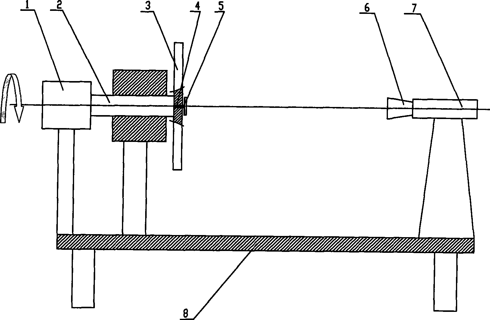
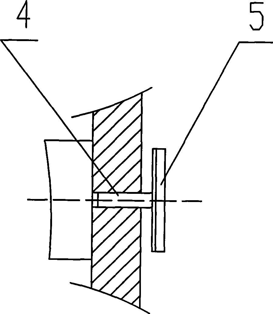
[0045] see figure 1 with figure 2 , the high-precision visual angle measuring device based on the dot matrix includes a frame 8, and the upper side of the workbench of the frame 8 is provided with a driving part 1, and the driving part 1 is a stepping motor or a servo motor, and the indexing accuracy is high; the driving part 1 The output end of the rotating part 2 is connected to the rotating part 2, and the other end of the rotating part 2 is connected to the tested rotating disk 3. A standard target 5 is coaxially installed on the outer surface of the tested rotating disk 3 through the positioning shaft 4; on the other side of the workbench A CCD camera 7 is installed through the bracket, and the imaging lens 6 of the CCD camera 7 is coaxially corresponding to the standard target 5;

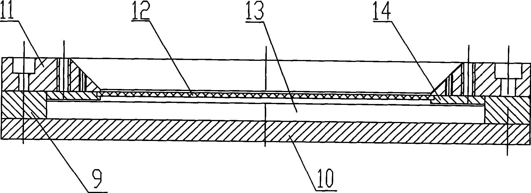
[0046] The standard target 5 includes a glass mirror shading plate 12, the glass mirror shading plate 12 is embedded in the inner side of the square frame-shaped fixing plate 11, and is fixe...

Embodiment 2

[0064] The distance between the standard target and the imaging lens is 0.75-20 meters. Others are with embodiment 1.

[0065] When used for large-angle measurement, the measurement range is 0°~360°, and the measurement accuracy is 2 arc seconds. For example, when measuring the rotating platform of an astronomical telescope, the standard target 5 is first connected to the positioning axis 4 of the rotating disk 3 under test. Then, through the imaging lens, the standard target light point array image is obtained, and the image plane coordinates (x, y) of 29×29 light points are obtained through the feature point detection algorithm, and the formula (u, v) of the object plane coordinates (u, v) is obtained 1), (2):

[0066] u=a 0 +a 1 x+a 2 y+a 3 x 2 +a 4 the y 2 +a 5 xy+a 6 x 3 +a 7 the y 3 +a 8 x 2 y+a 9 xy 2 (1)

[0067] +a 10 x 4 +a 11 the y 4 +a 12 xy 3 +a 13 x3 y+a 14 x 2 the y 2

[0068] v=b 0 +b 1 x+b 2 y+b ...


PUM


Abstract

The invention relates to a high precision visual angle measuring device which can measure minute angle and large angle, is not sensitive to the center jump and the like of a rotating part, and is based on dot matrix. The angle measuring device is provided with a stander working table which is provided with a driving element at one side, and the output end of the driving element is connected with the rotating part; the other end of the rotating part is connected with a rotating disc to be measured, and a standard target is coaxially arranged on the outer side of the rotating disc to be measured by a locating shaft; the other side of the working table is provided with a CCD video camera, an imaging lens of which is coaxially corresponding to the standard target; the standard target comprises a glass mirror occluder, a pane shaped fixing plate and a splint, wherein, an LED light source plate is arranged in a cavity between the glass mirror occluder, a liner plate and the splint; the glass mirror occluder is uniformly distributed with light holes transversely and longitudinally. The device can realize non-contact angular measure, the inaccuracy of measurement is less than 2 seconds of arc, the measuring range is 0-360 degrees, and the real-time control is carried out; furthermore, the angle measuring device is not sensitive to the error of the measured points, the rotating center jump and the long time temperature variation.

Description

technical field [0001] The invention relates to a high-precision angle measuring device that can measure small angles and large angles, and is insensitive to center runout of rotating parts. Background technique [0002] At present, angle measurement is an important part of geometric measurement technology, and its development is relatively complete. The comprehensive application of various measurement methods has made the measurement accuracy reach a very high level. Angle measurement technology can be divided into static measurement and dynamic measurement. For static measurement technology, the current main task is focused on how to improve measurement accuracy and measurement resolution. With the development of industry, there are more and more requirements for measuring the amount of rotation. Therefore, people have done a lot of research on the problem of measuring the rotation angle of rotating objects on the basis of static angle measurement, and many new angle meas...

Claims


Application Information

Patent Timeline
Patent Type & Authority Applications(China)
IPC IPC(8): G01B11/26
Inventor 李为民李晓峰
Owner UNIV OF SCI & TECH OF CHINA
Why Eureka
Try Eureka