Check patentability & draft patents in minutes with Patsnap Eureka AI!

Synchronous rectifier

A synchronous rectification and circuit technology, applied in electrical components, conversion devices for converting AC power input to DC power output, output power, etc. performance, easy connection and use, high power efficiency

Active Publication Date: 2011-04-27
TEN PAO ELECTRONICS HUIZHOU
View PDF1 Cites 0 Cited by
  • Summary
  • Abstract
  • Description
  • Claims
  • Application Information

AI Technical Summary

Problems solved by technology

Method ① can only be used in a circuit where the secondary voltage of the transformer is always a square wave, and the voltage and current are in the same phase. The voltage-driven synchronous rectification cannot be used in the excited power supply or the resonant soft switching power supply
Method ② can be applied to all types of power supplies, but a current transformer for detecting current is required to detect the current flowing through the secondary synchronous rectification field effect transistor. The patent application number 02121622.3 discloses a synchronous rectifier using a current driving method, but The current transformer has 4 windings, the winding of the current transformer is more difficult, the circuit is also more complicated, the cost is high, and it is not conducive to production. When designing switching power supplies with different output voltages, it is necessary to use current transformers with different winding turns. Manufacturing Difficulty increases; method 3 can not be applied except that the voltage and current of the transformer secondary voltage and current are different from the power supply, other synchronous rectification can be realized, but some integrated circuits can only be applied in discontinuous operation mode (DCM mode) or quasi-resonant mode (QR Mode), some integrated circuits can work in discontinuous mode (DCM mode), quasi-resonant mode (QR mode), continuous mode (CCM mode), but the control circuit module is more complicated
When the power supply voltage of the integrated circuit is 12V, the static working current is generally greater than 5mA, and the static power consumption is greater than 60mW, which may make the static power consumption of the entire power supply exceed the requirements of energy-saving standards.
The conduction time of the synchronous rectification FET and the conduction time of the primary switch must have enough dead time, which must exceed 500nS dead time, otherwise it is easy to be interfered, resulting in the failure of the synchronous rectification function and abnormal power output. If the dead time is too long, the conduction time of the parasitic fast recovery diode of the field effect transistor will be relatively long, because the conduction voltage drop of the fast recovery diode generally reaches more than 1V, so the loss is very high and the efficiency is reduced. the temperature will be higher
In addition, the connection of the synchronous rectification field effect tube must be at a specific position, and the position cannot be changed at will, otherwise, the synchronous rectification function cannot be realized

Method used


Image

  • Synchronous rectifier
  • Synchronous rectifier
  • Synchronous rectifier

Examples


Embodiment approach 1

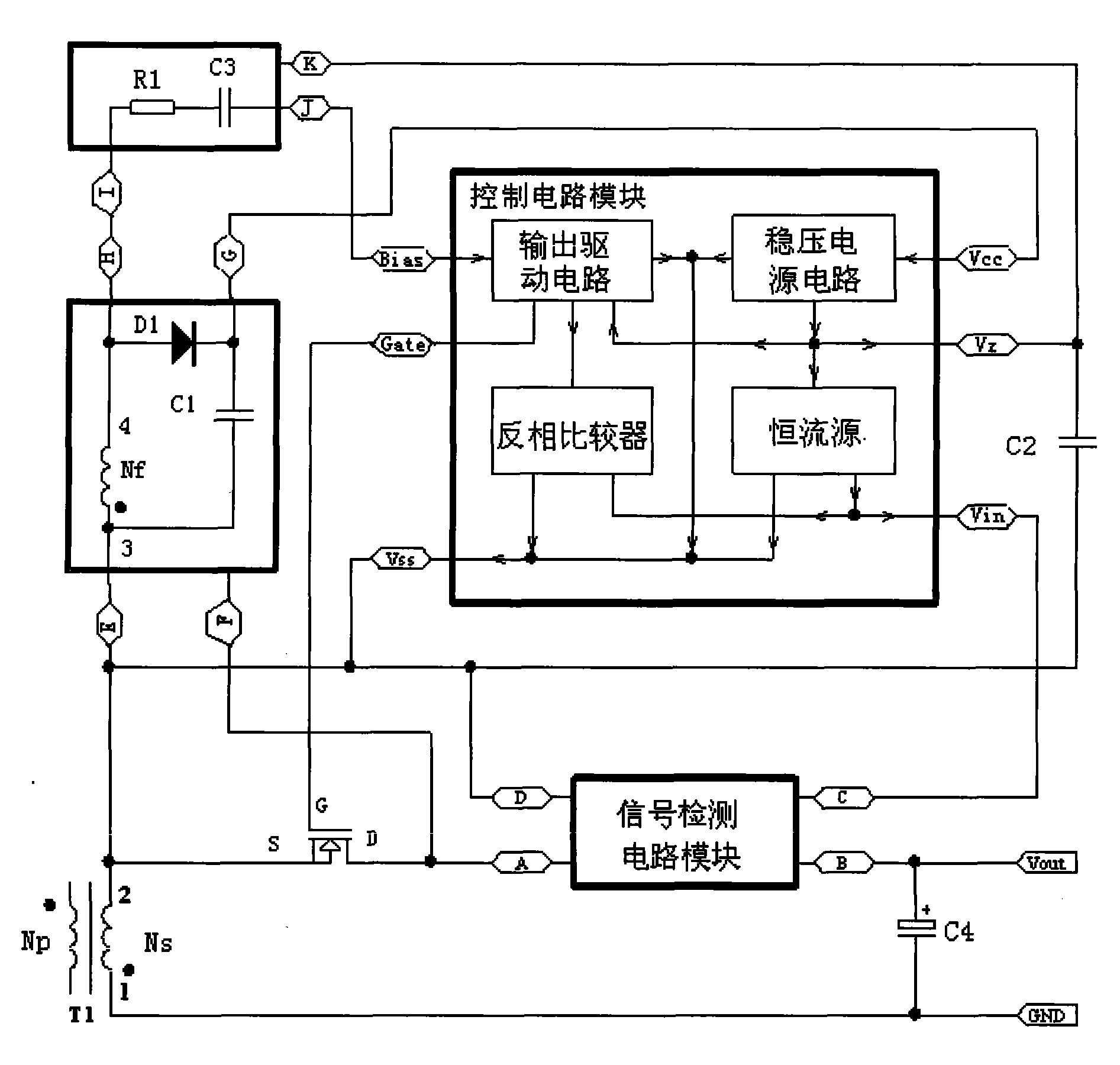
[0043] The implementation is as attached figure 2 , its working principle is that the voltage phase of the port 4 of the secondary auxiliary power supply winding Nf of the high frequency transformer T1 is the same as that of the port 2 of the secondary winding Ns of the high frequency transformer T1, when the voltage of the port 2 of the secondary winding Ns is positive, the secondary The voltage at port 4 of the secondary auxiliary power supply winding Nf is also positive, rectified by the rectifier diode D1, filtered by the filter capacitor C1, and then output through port D to supply power to the control circuit module.

[0044] When the output of the switching power supply is at no-load or light-load, the duty cycle of the primary switching tube of the switching power supply is very small, and the energy obtained by the secondary auxiliary power supply winding Nf of the high-frequency transformer T1 is very small, and this part of energy is obtained by the control circuit ...

Embodiment approach 2

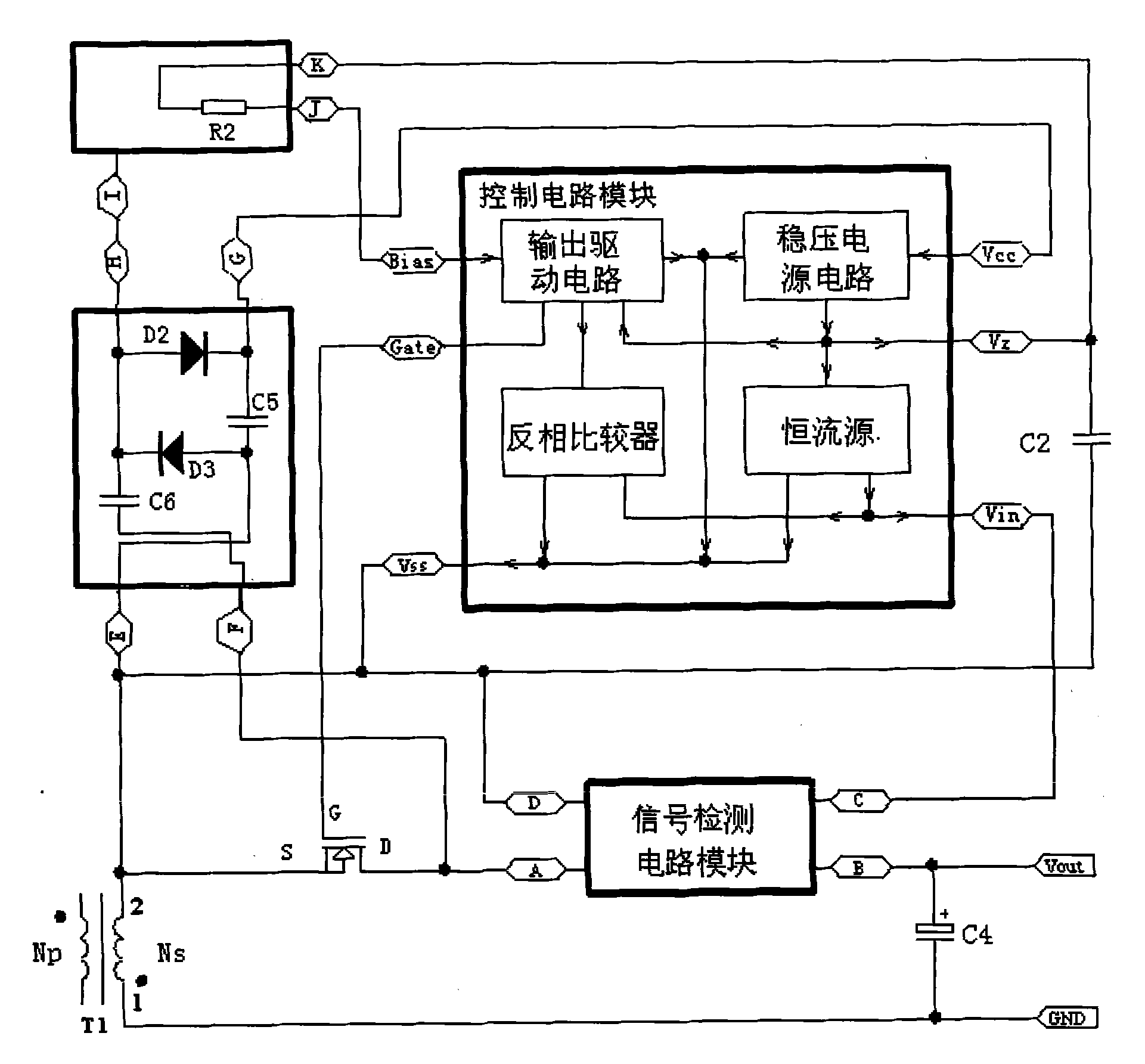
[0045] Embodiment 2 is attached image 3 , its working principle is that when the field effect transistor Q1 is turned on or the parasitic fast recovery diode in the field effect transistor Q1 is turned on, the drain D voltage of the field effect transistor Q1 is higher than the source S voltage, and the drain D voltage of the field effect transistor Q1 passes through The coupling capacitor C6 inside the auxiliary power circuit module supplies power to the control circuit module after being rectified by the rectifier diode D2 and filtered by the filter capacitor C2 after the current is limited and stepped down. When the FET Q1 is turned off or the parasitic fast recovery diode in the FET Q1 is turned off, the charge stored in the coupling capacitor C6 passes through the freewheeling diode D3, the secondary winding of the high frequency transformer T1, the output filter capacitor C4, the output load and signal detection Port B and port A of the circuit module are reversely disc...


PUM


Abstract

The invention relates to a switching power field, which particularly relates to a circuit used for driving N channel MOSFETs that are used for replacing rectifier diodes at the secondary side of a switching power high-frequency transformer to realize synchronous rectification. The synchronous rectification circuit comprises a signal detecting circuit module, a control circuit module, an auxiliarysupply circuit module and a biasing circuit module; the control circuit module comprises a voltage-stabilized circuit, a constant flow source, an invert comparator and an output drive circuit that are connected with each other by signals. The invention has the advantages of simple circuit and broad application range; the circuit of the invention can drive the N channel MOSFETs used for replacing the rectifier diodes to realize synchronous rectification when the switching power has light load, thus reducing the power consumption when in light load; the dead time kept between the breakover timeof the N channel MOSFETs and the breakover time of a primary switching tube is reduced to the utmost extent, thus reducing the consumption of the breakover time, improving the efficiency of the powersupply and achieving the energy-consumption requirement.

Description

technical field [0001] The invention relates to the field of switching power supplies, in particular to a circuit for driving an N-channel field effect transistor replacing a rectifying diode on the secondary side of a high-frequency transformer of a switching power supply to realize synchronous rectification. Background technique [0002] At present, the technologies for realizing the synchronous rectification of the secondary side of the switching power supply high-frequency transformer mainly include: ①voltage-driven synchronous rectification; ②current self-driven synchronous rectification; ③using a dedicated synchronous rectification integrated circuit to detect the D (drain) and The voltage between S (source) or the rising edge and falling edge of the voltage waveform, after the internal processing of the integrated circuit, outputs the signal to control the opening or closing of the field effect tube, and realizes the opening or closing of the field effect tube and the ...

Claims


Application Information

Patent Timeline
Patent Type & Authority Patents(China)
IPC IPC(8): H02M7/217
Inventor 洪光椅
Owner TEN PAO ELECTRONICS HUIZHOU
Features
  • R&D
  • Intellectual Property
  • Life Sciences
  • Materials
  • Tech Scout
  • Unparalleled Data Quality
  • Higher Quality Content
  • 60% Fewer Hallucinations
Learn More