
Light emitting device for use in therapeutic and/or cosmetic treatment

A technology for treating areas and moving devices, applied in the field of phototherapy agents

Inactive Publication Date: 2009-05-13
鲁米克尔有限公司
View PDF11 Cites 11 Cited by
  • Summary
  • Abstract
  • Description
  • Claims
  • Application Information

AI Technical Summary

Problems solved by technology

However, it is desirable to achieve large area illumination with other types of light sources, which have a more localized

Method used


Image

  • Light emitting device for use in therapeutic and/or cosmetic treatment
  • Light emitting device for use in therapeutic and/or cosmetic treatment
  • Light emitting device for use in therapeutic and/or cosmetic treatment

Examples


Embodiment Construction

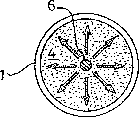
[0064] figure 1 The mobile device is intended to deliver electromagnetic radiation to a patient's skin area as part of a medical and / or cosmetic treatment.

[0065] The device comprises a diffusing element 1 in the form of a disc of diffusing material. The diffusing material may be any suitable translucent material, such as a suitable plastic. In this example, the light diffusing material is nylon 66, clear plastic, acetate or silicone.

[0066] The bottom surface of the diffusing element 1 defines a flat circular output surface 2 through which the device emits light and which, when in use, covers the area to be treated. The upper surface 4 of the disc 1 may have a reflective coating for reflecting light that would otherwise escape from the top of the disc 1 and return down towards the output surface 2 .

[0067] The device of this embodiment has a single light source in the form of a centrally mounted light emitting diode (LED) 6 . The LEDs 6 are integrally embedded in th...


PUM


Abstract

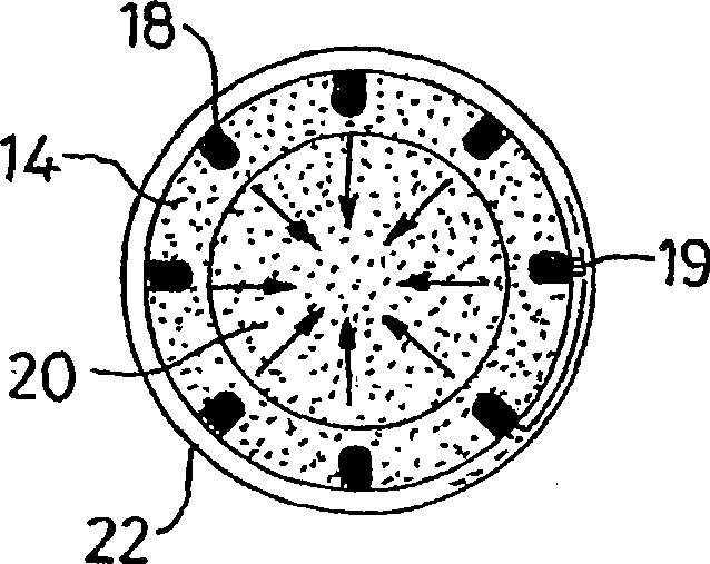
An ambulatory device for use in therapeutic and / or cosmetic treatment has a localised light source such as an LED (e.g. 6; 19; 46; 119; 219). Light from the source is output through an output surface which, in use, covers the area to be treated, and light is distributed over that surface by means of a diffusing member (e.g. 14; 114; 214) of which the output surface may form an integral part.

Description

technical field [0001] The present invention relates to devices for use in medical and / or cosmetic treatments, in particular for a treatment involving the exposure of parts of the body to electromagnetic radiation. The invention also relates to such devices and phototherapeutic agents for use therewith. Background technique [0002] Light can be used to treat a variety of diseases. When light alone is used to treat a disease, the treatment is called phototherapy. Light can be used in combination with drugs, in which case the treatment is called photodynamic therapy (PDT). [0003] These therapies can be used to treat a large number of dermatological and medical diseases. In PDT, a light-sensitive therapeutic agent called a photopharmaceutical is supplied externally or internally to the area of ​​the body to be treated. The area is then exposed to light of the appropriate frequency and intensity to activate the photopharmaceutical. A variety of photopharmaceuticals are c...

Claims


Application Information

Patent Timeline
Patent Type & Authority Applications(China)
IPC IPC(8): A61N5/06
CPCA61N2005/063A61N2005/0652A61N2005/0645A61N5/062A61N5/0601A61N5/06
Inventor 埃弗尔·戴维德·威廉·塞缪尔詹姆斯·弗格森安德鲁·保罗·麦克尼尔
Owner 鲁米克尔有限公司
Learn More