Discharge door mechanism of stirring machine

A discharge door and mixer technology, applied in the direction of mixer accessories, mixers, dissolving, etc., can solve the problems of accelerated discharge door wear, material leakage, distance can not be adjusted, etc., to achieve the effect of solving the problem of unloading

Inactive Publication Date: 2009-05-20
张家港市繁昌机械有限公司
View PDF7 Cites 4 Cited by
  • Summary
  • Abstract
  • Description
  • Claims
  • Application Information

AI Technical Summary

Problems solved by technology

The rotation angle of the discharge door is adjusted by controlling the expansion and contraction of the oil cylinder. Since the distance between the discharge door and the discharge plate cannot be adjusted, the thickness of the discharge door decreases after long-term friction, and the discharge plate and the discharge door There will be a large gap between them, which will cause the material to leak out or get stuck between the discharge plate and the discharge door during the working process, which will accelerate the wear of the discharge door and even block the discharge door.
When a power failure occurs in the workplace, the discharge door cannot be opened manually, and the materials in the mixer cannot be cleaned up in time. If the materials are not cleaned for a long time, the materials will agglomerate and it will be more difficult to clean up.

Method used


Image

  • Discharge door mechanism of stirring machine
  • Discharge door mechanism of stirring machine

Examples


Embodiment Construction

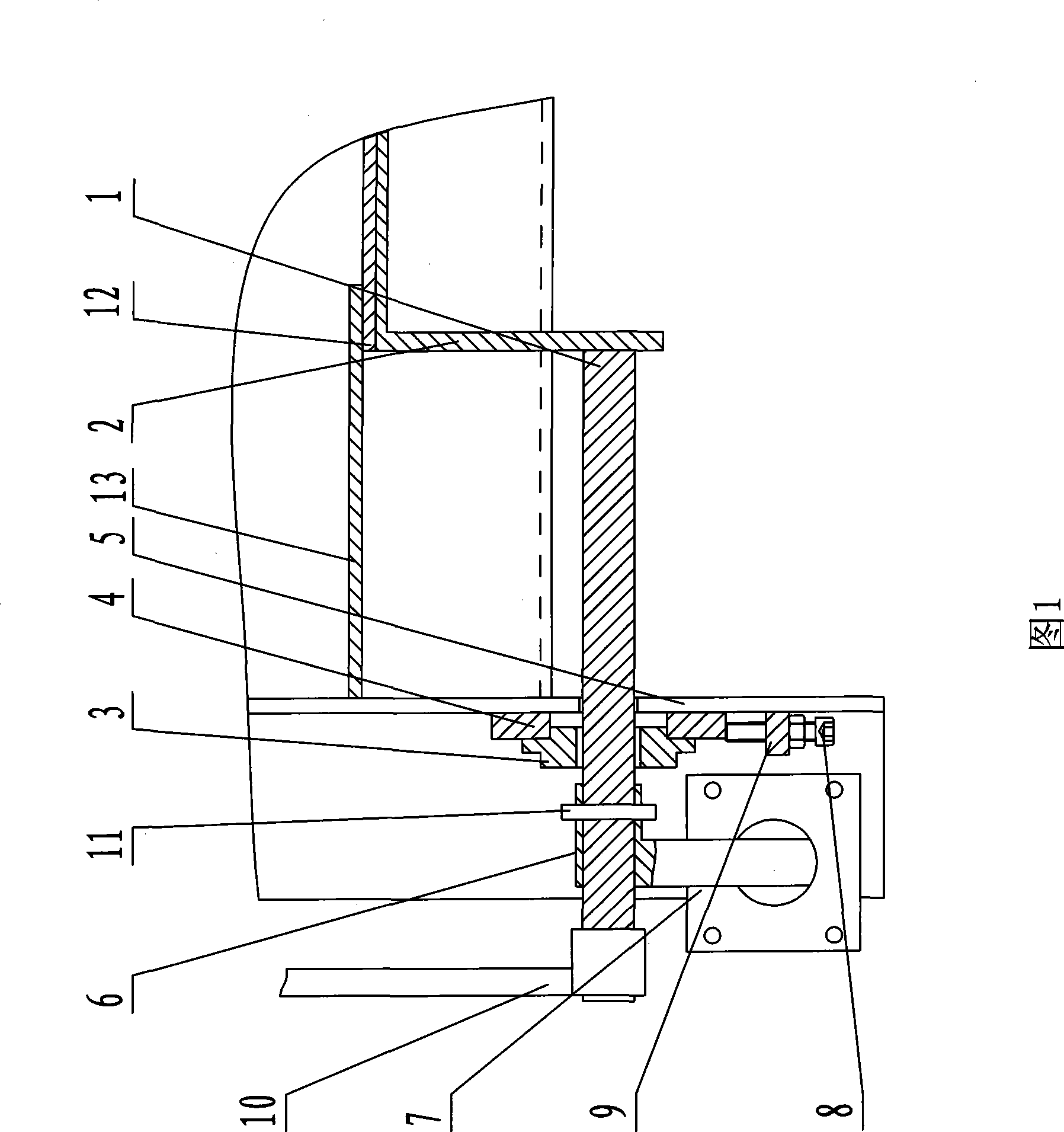
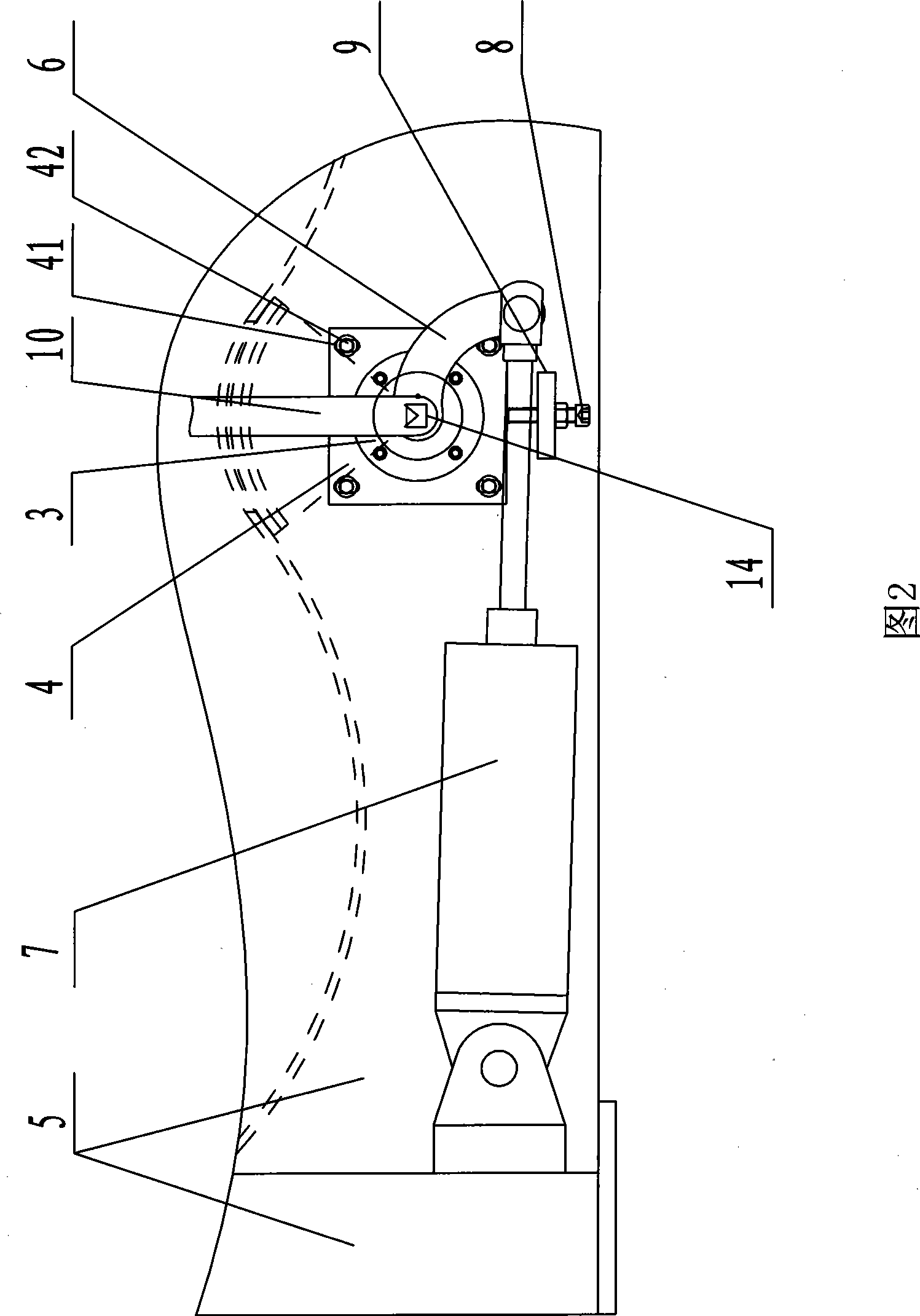
[0013] The structure and working principle of the discharge door device of the mixer of the present invention will be further described in detail below in conjunction with the accompanying drawings.

[0014] As shown in Figures 1 and 2, a discharge door device for a mixer includes a wallboard 5, a discharge door main shaft 1, a discharge door 2 arranged on the discharge door main shaft 1, and the discharge door main shaft 1 is arranged on Inside the bearing with seat 3, the bearing with seat 3 is arranged on the bearing mounting plate 4, and several waist holes 41 are arranged on the bearing mounting plate 4, and bolts 42 fix the bearing mounting plate 4 on the wallboard 5 through the waist holes 41 Above, a rocker arm 6 is set on the main shaft 1 of the discharge door. The rocker arm 6 is located outside the bearing 3 with a seat. The oil cylinder 7 is hinged on the wallboard 5 and is hinged with the rocker arm 6. The lower side of the bottom is provided with an adjusting bol...


PUM


Abstract

The invention discloses a discharging door device of a stirring machine with adjustable distance between a discharging door and a discharging board, which comprises a wallboard, a discharging door main shaft, and the discharging door arranged on the discharging door main shaft, wherein the discharging door main shaft is arranged in a seated bearing which is arranged on a bearing mounting board; a rocking arm is sleeved on the discharging door main shaft and is positioned on the outside of the seated bearing; an oil cylinder is hinged on the wallboard and is hinged with the rocking arm; the bearing mounting board is provided with a plurality of waist holes; the bearing mounting board is fixed on the wallboard by bolts through the waist holes; the underside of the bearing mounting board is provided with an adjusting bolt which passes through a permanent seat fixed on the wallboard to contact the bearing mounting board; and the adjusting bolt is connected with the permanent seat through screw threads. The discharging door device is applicable to a discharging device of the stirring machine.

Description

technical field [0001] The invention relates to a discharge door device of a mixer. Background technique [0002] At present, mixers are widely used. The discharge door device generally includes the discharge door main shaft, the discharge door set on the discharge door main shaft, the bearing with seat sleeve is set on the discharge door main shaft and set on the bearing mounting plate, the bearing installation The plate is fixed on the wallboard, and a rocker arm is set on the main shaft of the discharge door. The rocker arm is fixed on the main shaft of the discharge door through a taper pin. The rocker arm is located outside the bearing with seat, and the oil cylinder is hinged on the wall board. And hinged with the rocker arm. The rotation angle of the discharge door is adjusted by controlling the expansion and contraction of the oil cylinder. Since the distance between the discharge door and the discharge plate cannot be adjusted, the thickness of the discharge door d...

Claims


Application Information

Patent Timeline
Patent Type & Authority Applications(China)
IPC IPC(8): B01F15/02
Inventor 倪玉标杨建国刘宗翔
Owner 张家港市繁昌机械有限公司
Why Eureka
Try Eureka