
Integrated alignment packaging structure for detector circuit board and optical waveguide chip

A packaging structure and circuit board technology, applied in the coupling of optical waveguides, light guides, optics, etc., can solve the problems of low precision, poor reliability, and large human errors, and achieve good mechanical properties, low cost, and easy coating.

Active Publication Date: 2019-04-26
CHINA SCI PHOTON CHIP HAINING TECH CO LTD
View PDF6 Cites 0 Cited by
  • Summary
  • Abstract
  • Description
  • Claims
  • Application Information

AI Technical Summary

Problems solved by technology

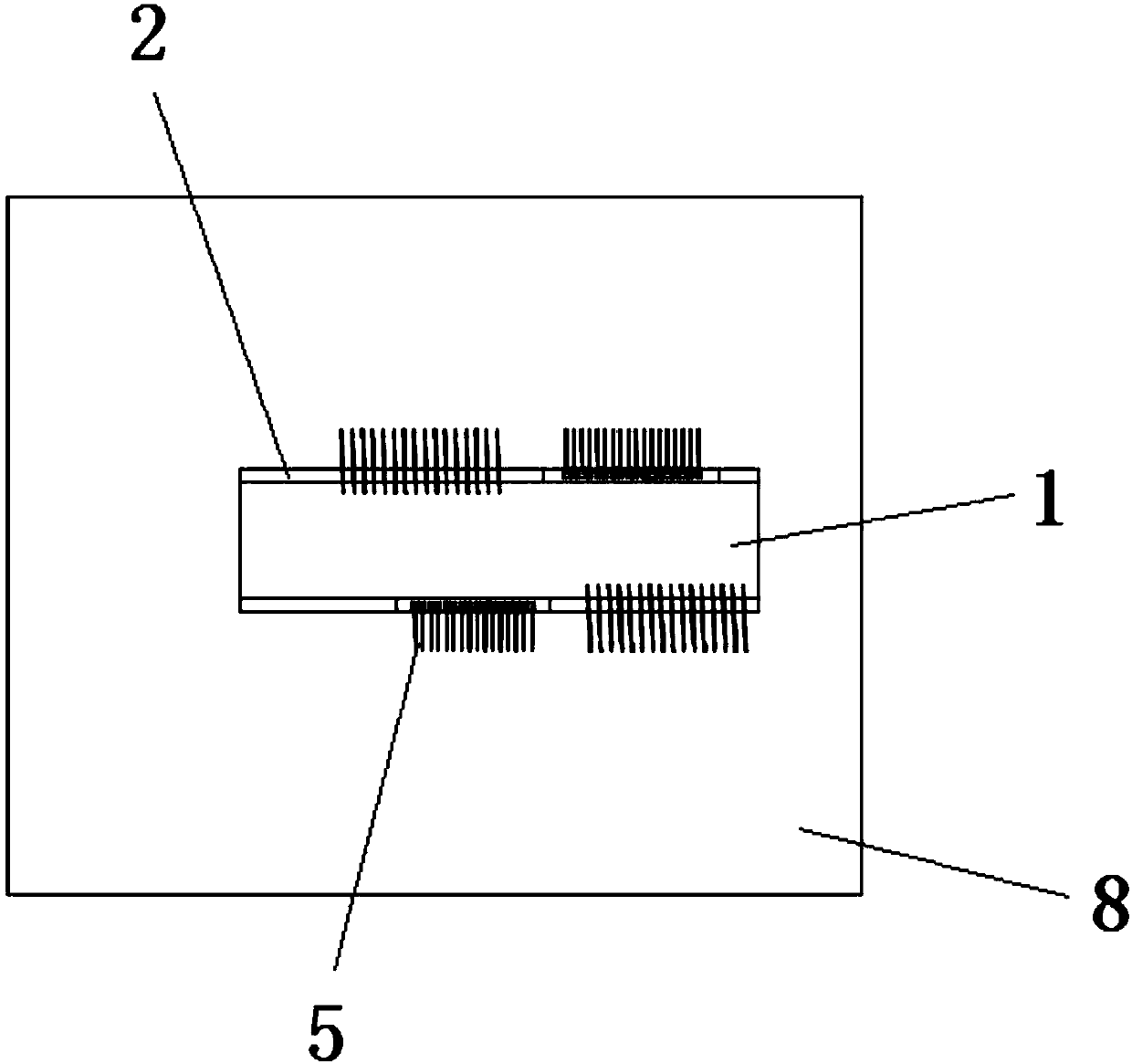
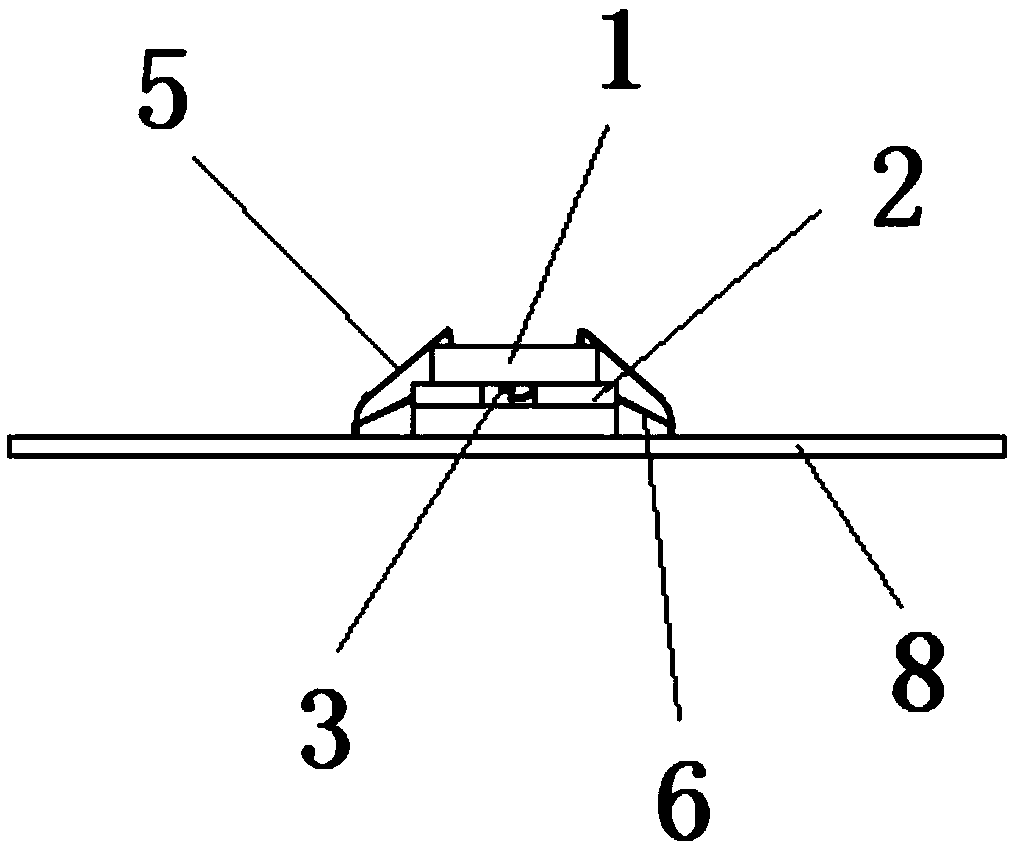
[0004] Therefore, the technical problem to be solved by the present invention is to overcome the defects of large human error, low precision and poor reliability in the alignment of the detector circuit board and the optical waveguide chip in the prior art, so as to provide a high alignment precision and reliability, easy to operate Convenient and fast integrated alignment package structure of detector circuit board and optical waveguide chip

Method used


Image

  • Integrated alignment packaging structure for detector circuit board and optical waveguide chip
  • Integrated alignment packaging structure for detector circuit board and optical waveguide chip
  • Integrated alignment packaging structure for detector circuit board and optical waveguide chip

Examples


Embodiment Construction

[0029] The technical solutions of the present invention will be clearly and completely described below in conjunction with the accompanying drawings. Apparently, the described embodiments are some of the embodiments of the present invention, but not all of them. Based on the embodiments of the present invention, all other embodiments obtained by persons of ordinary skill in the art without making creative efforts belong to the protection scope of the present invention.

[0030] In addition, the technical features involved in the different embodiments of the present invention described below may be combined with each other as long as there is no conflict with each other.

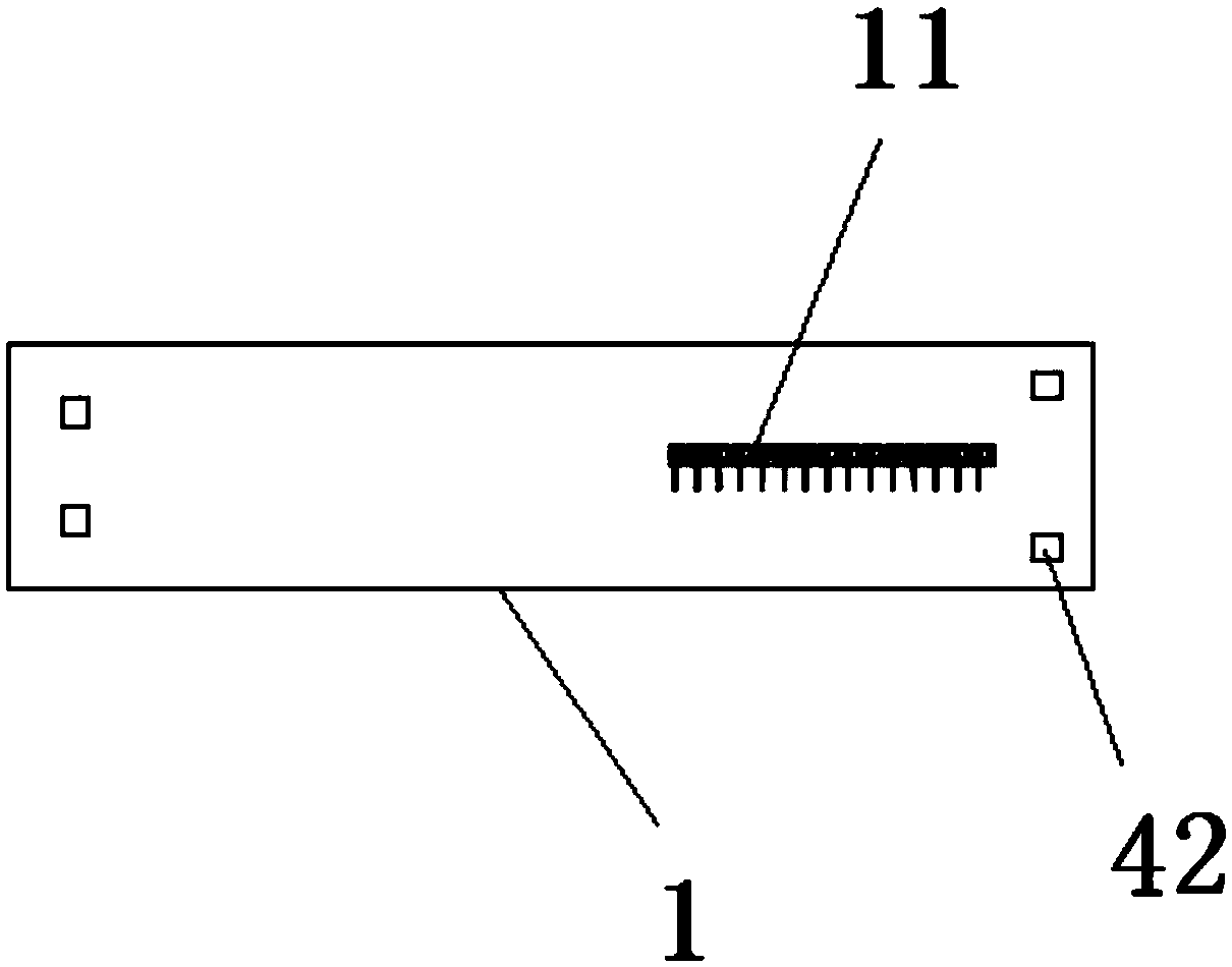
[0031] like figure 1 A specific implementation of the integrated alignment package structure of the detector circuit board and the optical waveguide chip shown in -4, including the detector circuit board 1 and the optical waveguide chip 2, the detector circuit board 1 is flip-chip mounted on the optical waveg...


PUM


Abstract

The invention relates to the technical field of chip packaging, in particular to an integrated alignment packaging structure for a detector circuit board and an optical waveguide chip. The integratedalignment packaging structure comprises the detector circuit board (1) and the optical waveguide chip (2); the detector circuit board (1) is inversely installed on the optical waveguide chip (2); thesurface, facing the detector circuit board (1), of the optical waveguide chip (2) is covered with a supporting body (3), and a welding point is pre-formed on the supporting body (3) and has a meltingstate for automatically correcting and aligning the detector circuit board (1) and the optical waveguide chip (2) and a fixing state for connecting the detector circuit board (1) and the optical waveguide chip (2) after being cured. The integrated alignment packaging structure for the detector circuit board and the optical waveguide chip is high in alignment precision and reliability and convenient to operate.

Description

technical field [0001] The invention relates to the technical field of chip packaging, in particular to an integrated alignment packaging structure of a detector circuit board and an optical waveguide chip. Background technique [0002] In recent years, with the explosive growth of solid-state lidar, the demand for solid-state optical waveguide modules has also increased, and the requirements have become more stringent. Low cost, high speed, and high reliability have become the constant pursuit of innovation. At present, mainstream packaging methods are based on packages formed by combinations of reflective prisms, lenses, filters, or metal supports. The packaging process includes complex optical path designs. , cumbersome and non-reproducible coupling and alignment process, making the cost of the optical module high and the reliability low. [0003] Since the light output from the phase monitoring point on the surface of the optical waveguide chip has a certain divergence,...

Claims


Application Information

Patent Timeline
Patent Type & Authority Applications(China)
IPC IPC(8): G02B6/42
CPCG02B6/4237G02B6/428
Inventor 仝飞刘敬伟姜磊
Owner CHINA SCI PHOTON CHIP HAINING TECH CO LTD
Learn More