Clamp for mounting component and mounting structure of component

A technology for installation and components, which is applied in the direction of vehicle components, transportation and packaging, and special positions of vehicles, etc. It can solve the problems that the elastic locking feet cannot pass through the installation holes and cannot assist the fixing of the armrest, etc., and achieve a small locking width , Rigidity reduction, load reduction effect

Active Publication Date: 2009-05-20
TOYODA GOSEI CO LTD
View PDF3 Cites 15 Cited by
  • Summary
  • Abstract
  • Description
  • Claims
  • Application Information

AI Technical Summary

Problems solved by technology

Therefore, it is possible that the elastic locking foot (14) cannot pass through the mounting hole (H), and the auxiliary armrest cannot be formally fixed in the mounting hole (H)

Method used


Image

  • Clamp for mounting component and mounting structure of component
  • Clamp for mounting component and mounting structure of component
  • Clamp for mounting component and mounting structure of component

Examples


Embodiment Construction

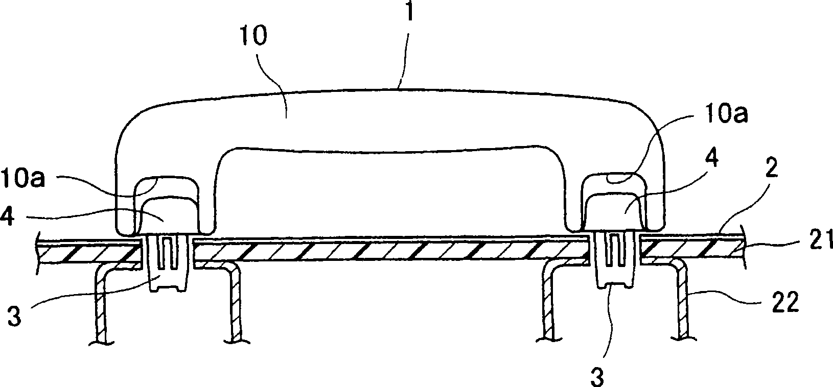
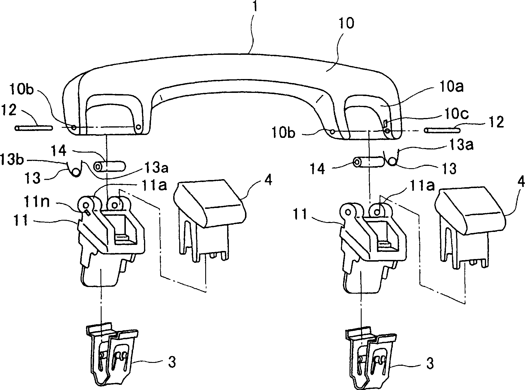
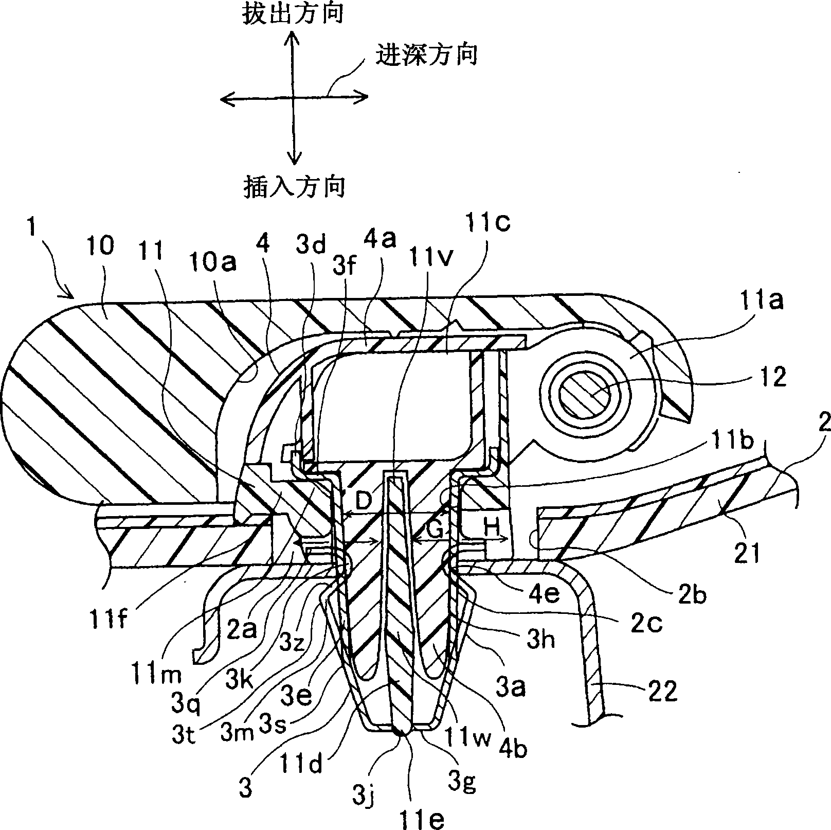
[0033] Embodiment 1 according to the present invention will be described with reference to the drawings. figure 1 It is a front view of the installation structure for attaching the auxiliary armrest to the side panel of the vehicle. figure 2 It is an exploded oblique view of the mounting structure. Such as figure 1 , figure 2 As shown, the auxiliary grab bar 1 is mounted on the vehicle side panel 2 using the clamp 3 and the cover portion 4 .

[0034]The auxiliary armrest 1 includes: an armrest body 10 ; and bases 11 provided at both ends of the armrest body 10 and supporting the armrest body 10 rotatably. Both ends of the armrest main body 10 have recesses 10 a for accommodating the base 11 . The shaft hole 10b is opened on the side wall of the recessed portion 10a. The armrest body 10 is rotatably supported on the base 11 by inserting the shaft 12 into the shaft hole 10 b and the hole of the bearing portion 11 a provided on the base 11 . In addition, a spring 13 is ...


PUM


Abstract

The invention provides a clamp used for installing parts and the installation structure of the parts. The clamp (3) comprises a pair of lateral walls (3e), with the front end parts (3g) of the lateral walls being mutually connected; an inner space (3b) which is between the paired lateral walls; and an opening (3c) which is communicated with the inner space at the base end part (3d). An elastic blocking part (3a) blocked in an installing hole and a step part (3f) maintained on an auxiliary handrail are respectively arranged on the paired lateral walls. One end (3s) of the elastic blocking part is connected with the lateral wall, while the other end (3q) is a free end. The elastic blocking part is provided with a bending part (3t) which is provided with a dent (3k) that sags laterally towards the inner space relative to the end part and is blocked with the installing hole; and a sally (3m) that protrudes laterally relative to the dent (3k). The elastic blocking part is at least divided into a plurality of dividing pieces from the end part to the dent. By utilizing the structure, the clamp can be prevented from being pulled out from the installing hole.

Description

technical field [0001] The present invention relates to a jig used for mounting components such as vehicle interior components and a component mounting structure. Background technique [0002] The auxiliary armrest is a vehicle interior component having a function of stabilizing a passenger's body by holding it by hand, for example, when getting on and off the vehicle or when vibration occurs due to driving on a poor road surface. The auxiliary grab rail is installed on the side of the ceiling in the compartment of the vehicle. At present, when installing vehicle interior parts such as auxiliary armrests on the vehicle body side panel in the vehicle interior, there are, for example, the publications of JP-A-2001-130307, ​​JP-A-2003-226182 and JP-A-2001-277926. public constructs. [0003] In JP-A-2001-130307 Bulletin image 3 The structure disclosed in et al. is that on the armrest body (12) of the auxiliary armrest (10), an expansion and contraction member (16) is integral...

Claims


Application Information

Patent Timeline
Patent Type & Authority Applications(China)
IPC IPC(8): B60N3/02F16B19/10
Inventor 户谷千春佐久间纯行一濑信之寺冈寿美江
Owner TOYODA GOSEI CO LTD
Why Eureka
Try Eureka