
Batch allocating pore and method for predicting pore quantity

A hole and quantity technology, applied in electrical digital data processing, special data processing applications, instruments, etc., can solve the problems of difficult to judge the number of holes, not large enough, waste of manpower and time, etc., to achieve the effect of saving manpower

Inactive Publication Date: 2009-05-20
INVENTEC CORP
View PDF0 Cites 4 Cited by
  • Summary
  • Abstract
  • Description
  • Claims
  • Application Information

AI Technical Summary

Problems solved by technology

[0003] However, it is difficult to manually judge how many holes can be accommodated in the copper area
In addition, in the process of manually configuring the holes, sometimes it is found that the above-mentioned copper-laying area is not large enough after the holes are arranged in the above-mentioned copper-laying area, and the copper-laying must be re-placed, which is a waste of manpower and time

Method used


Image

  • Batch allocating pore and method for predicting pore quantity
  • Batch allocating pore and method for predicting pore quantity
  • Batch allocating pore and method for predicting pore quantity

Examples


Embodiment Construction

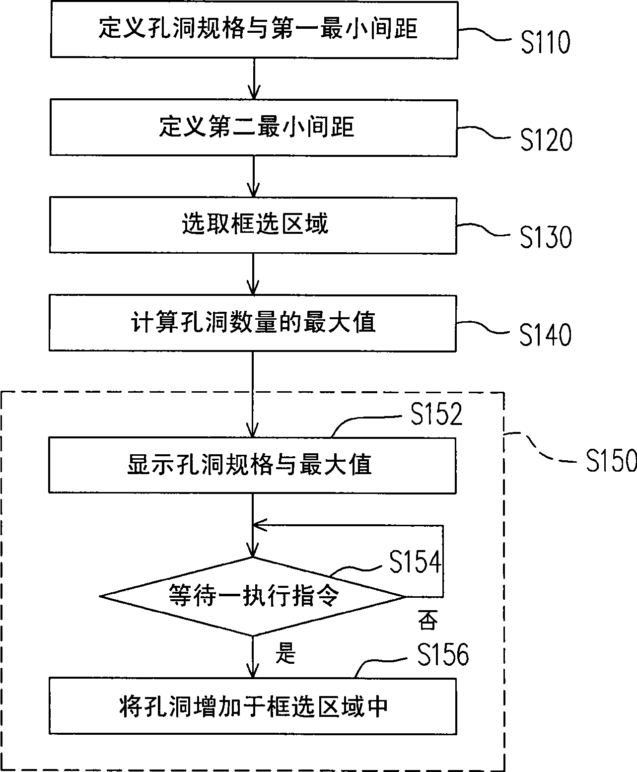
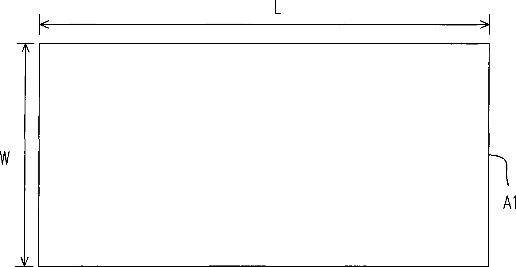
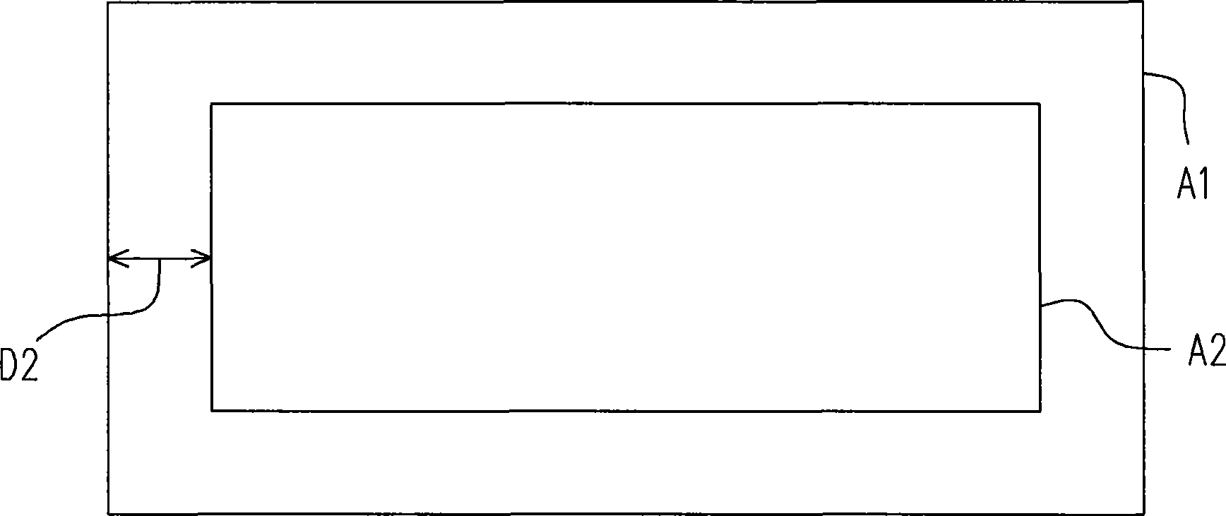
[0030] figure 1 A flowchart of a method for configuring holes for a batch according to an embodiment of the present invention. Figure 2A A schematic diagram of the copper area of ​​a circuit board. Please refer to figure 1 and Figure 2A , the copper-clad region A1 has a length L and a width W. When multiple holes H are to be configured on the copper laying area A1 (such as Figure 2D ), step S110 is first performed to define a first minimum distance D1 between at least one hole specification and adjacent holes H. For example, the hole specifications of the holes H and the first minimum distance D1 input by the user may be received, or the set values ​​may be automatically generated according to a preset specification table (nettype). In this embodiment, the hole specification includes, for example, the diameter O1 of the hole H. As shown in FIG.

[0031] Next, step S120 may be performed to define a second minimum distance D2 of each hole H relative to a trace (not show...


PUM


Abstract

The invention relates to a method for configuring holes in batch, which is suitable to configure a plurality of holes in a copper-pouring area of a circuit board. The method for configuring the holes in batch comprises: firstly, defining the specification of at least one hole and the first minimum spacing between adjacent holes; secondly, selecting a frame selection area on the copper-pouring area; thirdly, calculating the maximum number of the holes capable of being configured in the frame selection area according to the specification of the hole, the first minimum spacing and the area of the frame selection area; and fourthly, configuring the holes in the frame selection area according to the maximum value. Moreover, the invention also provides a method for predicting the number of the holes.

Description

technical field [0001] The present invention relates to a layout method, and in particular to a method of disposing holes in a copper laying area during layout. Background technique [0002] In the layout of printed circuit boards, it is often necessary to lay copper (AREAFILL) in a large area in some areas to provide electronic components for heat dissipation or grounding. Considering the electrical characteristics, such as electrostatic discharge (ESD) protection, enhanced current, etc., a sufficient number of holes must be arranged in the above-mentioned copper laying area to meet the requirements of the circuit on the printed circuit board. According to the operation procedure of the current layout, the holes are manually arranged in the above-mentioned copper laying area, and the holes are arranged one by one according to the required number of holes. [0003] However, it is difficult to manually judge how many holes can be accommodated in the copper pour area. In add...

Claims


Application Information

Patent Timeline
Patent Type & Authority Applications(China)
IPC IPC(8): G06F17/50
Inventor 何振东林梨燕廖敬浤陈心慧
Owner INVENTEC CORP
Learn More