Power supply switching device and network appliance

A power switching and network technology, applied in circuit devices, emergency power arrangements, data switching current sources, etc., can solve problems such as network equipment cannot continue to operate, and achieve the effect of improving power quality and avoiding power waste

Active Publication Date: 2009-05-20
UNIVERSAL SCIENTIFIC INDUSTRIAL (SHANGHAI) CO LTD
View PDF0 Cites 44 Cited by
  • Summary
  • Abstract
  • Description
  • Claims
  • Application Information

AI Technical Summary

Problems solved by technology

However, in order to improve the power supply quality of network equipment, it is still not enough to use Power over Ethernet technology alone. Once the Power over Ethernet module in the network equipment is damaged, the network equipment will not be able to continue to operate

Method used


Image

  • Power supply switching device and network appliance
  • Power supply switching device and network appliance
  • Power supply switching device and network appliance

Examples


Embodiment Construction

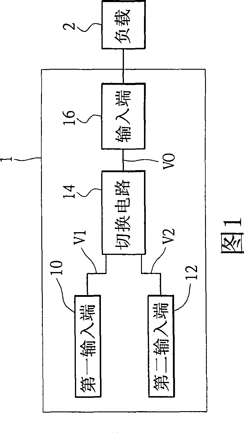
[0035] Please refer to FIG. 1 , which is a schematic diagram of the architecture of the network device of the present invention. The network equipment (not shown) of the present invention includes a power switching device 1 connected to a load 2 . The power switching device 1 includes a first input terminal 10 , a second input terminal 12 , an output terminal 16 and a switching circuit 14 .

[0036] Referring again to FIG. 1 , the first input terminal 10 can provide a first power supply wire (not shown) to be inserted. The second input end 12 can be provided for a second power supply wire (not shown) to be inserted. The output terminal 16 is connected to the load 2 and outputs an output voltage to the load 2 . The switching circuit 14 is connected to the first input terminal 10, the second input terminal 12 and the output terminal 16. The switching circuit 14 is inserted into the second input terminal 12 according to the second power supply wire head to cut off the output vo...


PUM


Abstract

The invention provides a power switching device for network equipment to switch the power of Ethernet (POE) or DC power supply to supply power to loads in the network equipment. The power switching device comprises a first input end into for a first wire head to be inserted, a second input end for a second wire head to be inserted, an output end for outputting output voltage, and a switching circuit connected with the first input end, the second input end and the output end, wherein the switching circuit is inserted into the second input end through the second wire head to cut off output voltage supplied by the first wire head and uses the second wire head to supply output voltage.

Description

technical field [0001] The present invention relates to a power switching device, in particular to a power switching device for switching Power Of Ethernet (POE) or DC power supply, and a network device using the switching device. Background technique [0002] The power required for the operation of general network equipment is usually obtained through an external power supply, and at the same time, the transmitted data is transmitted through the network cable. Therefore, a general network device has a network connection port and a power connection port for obtaining power and data required for operation. However, the architecture of this kind of network equipment needs to be additionally connected to a power supply for normal operation, which will result in additional cost of components and complicated wiring. Therefore, another Power Of Ethernet (POE) technology has been developed. The Power Of Ethernet (POE) technology adopts all the specifications in the IEEE 802.3af st...

Claims


Application Information

Patent Timeline
Patent Type & Authority Applications(China)
IPC IPC(8): H02J9/06H04L12/10
Inventor 叶洧豪
Owner UNIVERSAL SCIENTIFIC INDUSTRIAL (SHANGHAI) CO LTD
Why Eureka
Try Eureka