Contactor with peripheral surge restraining unit

A surge suppression and contactor technology, applied to emergency protection circuit devices, relays, electrical components, etc. for limiting overcurrent/overvoltage, which can solve the problem of wasted installation space of distribution boxes, unusable contactors, and easy breakage. open etc.

Active Publication Date: 2009-05-27
ZHEJIANG CHINT ELECTRIC CO LTD
View PDF0 Cites 3 Cited by
  • Summary
  • Abstract
  • Description
  • Claims
  • Application Information

AI Technical Summary

Problems solved by technology

First of all, because the contactor itself is not set or does not reserve enough space for the external surge suppression unit, so the surge suppression unit has no place to settle, and the installation space required by the contactor has to be expanded, which leads to the distribution box The waste of installation space even makes the contactor unusable in some occasions with limited space
The second is that the contactor itself is not equipped with a fixing device for installing an external surge suppression unit, so the surge suppression unit cannot be fixed, and unreliable and impermanent fixations such as adhesive paper bonding and terminal lap joints have to be used. Under the influence of vibration, temperature, humidity and other environments, the surge suppression unit is easy to fall off, so that the electrical connection between the surge suppression unit and the contactor is easily disconnected, which seriously affects the safety and reliability of the contactor product. , thus greatly limiting the use of contactor products

Method used


Image

  • Contactor with peripheral surge restraining unit
  • Contactor with peripheral surge restraining unit
  • Contactor with peripheral surge restraining unit

Examples


Embodiment Construction

[0020] Attached below Figure 1-7 The illustrated embodiment illustrates the contactor with surge suppression unit of the present invention in detail, and the present invention is not limited to the following description of the specific embodiment.

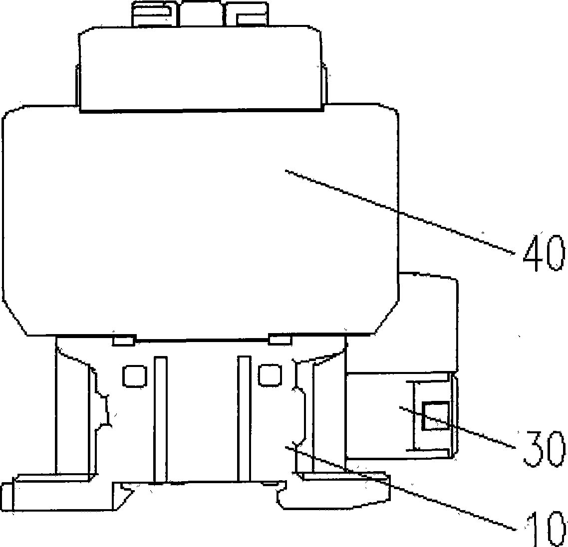
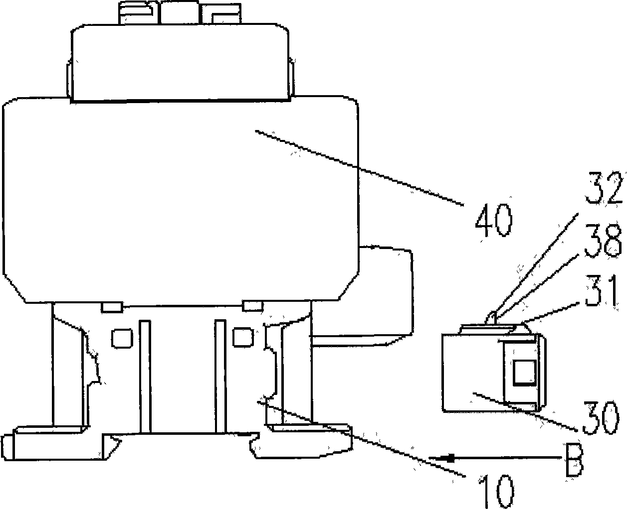
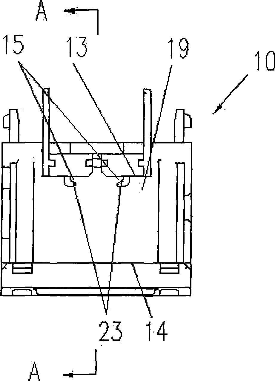
[0021] figure 1 is a schematic diagram of the appearance of an embodiment of the contactor of the present invention, figure 2 It is a schematic diagram of the installation principle of the surge suppression unit. like figure 1 , 2 As shown, the contactor of the present invention includes a base unit 10 and a base unit 40 located thereon, and components for realizing various functions of the contactor are arranged in the base unit 10 and the base unit 40 . The peripheral surge suppression unit 30 is installed and fixed in the upper dedicated space 12 outside the base unit 10 in a pluggable manner (such as image 3 shown). figure 1 What is shown is the state where the surge suppression unit 10 is plugged and fixed on the cont...


PUM


Abstract

The invention provides a contactor, which comprises a bed unit and a base unit, wherein a special space and a fixing device for installing and fixing a pluggable surge-inhibiting unit are prearranged outside one side of the bed unit; a supporting structure and a fixing structure are arranged on the outer wall of the special space of the bed unit; and another supporting structure matched with the supporting structure on the bed unit and another fixing structure matched with the fixing structure on the bed unit are arranged on the surge-inhibiting unit and are used for fixing the surge-inhibiting unit on the bed unit without freely falling away. The contactor solves a series of defects such as easy damage, short service life, waste of installation space, poor safety and poor reliability which are caused by the poor heat dissipation, unreliable fixation and other reasons of the prior surge-inhibiting unit, and provides the contactor with high reliability, small installation space, convenient assembly/disassembly and wider application.

Description

technical field [0001] The invention relates to a contactor with a surge suppression unit, in particular to a contactor with a space and a fixing device for an external surge suppression unit. Background technique [0002] The surge suppression unit is an important part to protect the contactor coil by suppressing the overvoltage, which is an important hidden danger of burning out the electronic components in the contactor, and the overvoltage is caused by the abnormality of the power grid. Therefore, the important role of the surge suppression unit is to protect the contactor from being burned out, prolong the service life of the contactor, and improve the safety level of the contactor. [0003] The surge suppression unit is composed of electronic components such as capacitors and fixed resistors installed in the contactor housing. Generally, fixed resistors are carbon film resistors, metal film resistors or carbon rod resistors. Among them, carbon film resistors and metal...

Claims


Application Information

Patent Timeline
Patent Type & Authority Applications(China)
IPC IPC(8): H02B1/01H01H45/00H02H9/04
Inventor 靳海富郭德鑫胡吉庆
Owner ZHEJIANG CHINT ELECTRIC CO LTD
Why Eureka
Try Eureka