Latch needle

A technology of latch needles and needle bars, which is applied in the field of latch needles and can solve problems such as the reduction of the opening width of the needle hook

Active Publication Date: 2009-06-03
KARL MAYER STOLL R&D GMBH
View PDF1 Cites 2 Cited by
  • Summary
  • Abstract
  • Description
  • Claims
  • Application Information

AI Technical Summary

Problems solved by technology

However, the tapering of the shank of this known needle leads to a reduction in the opening width of the hook, which is disadvantageous especially when inserting several yarns or a yarn thicker than the hook dimension into the hook Impact

Method used


Image

  • Latch needle
  • Latch needle
  • Latch needle

Examples


Embodiment Construction

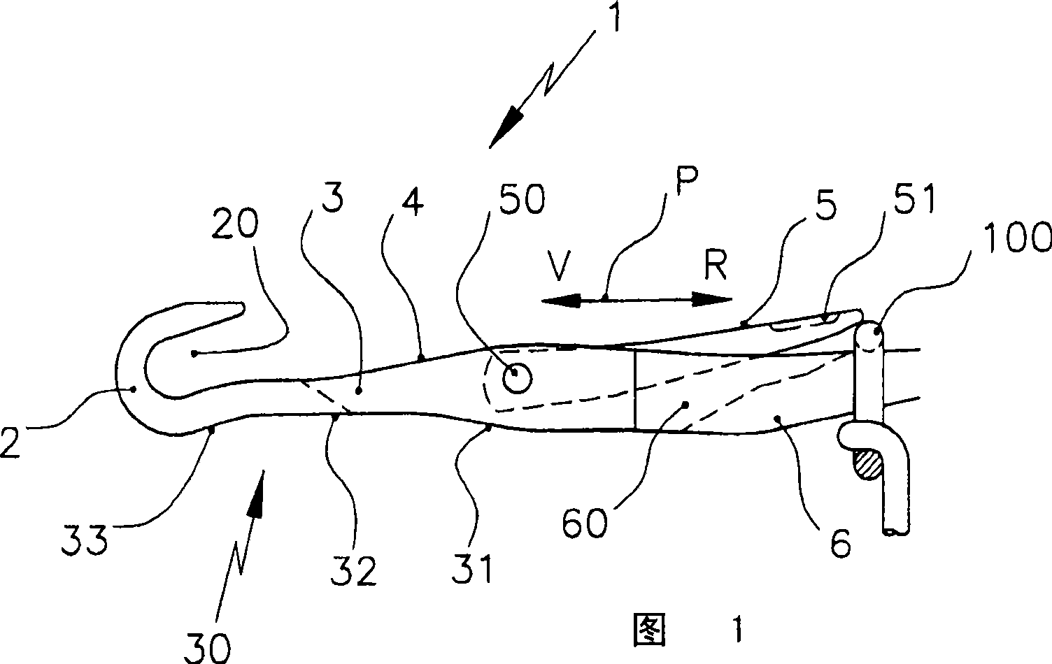
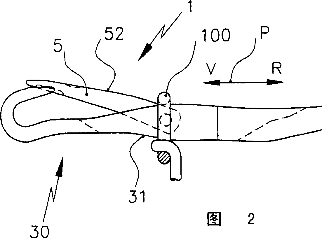
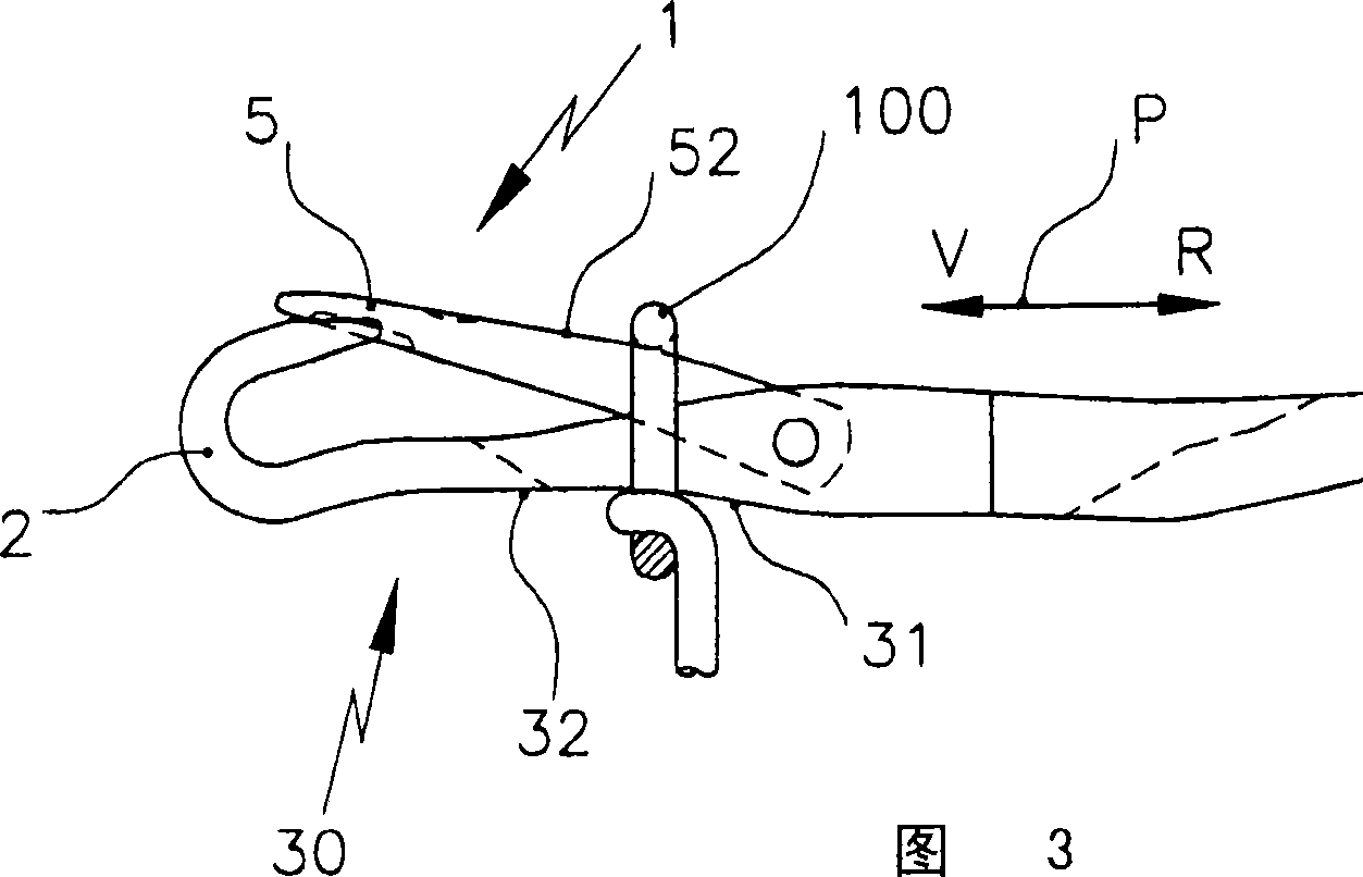
[0018] The latch needle 1 shown in FIGS. 1 to 5 has a hook 2 which encloses a hook space 20 . The needle hook 2 is molded onto the needle neck 3 , which transitions via the needle breast 4 into the needle shaft 6 . On the needle bar 6 , the latch 5 is mounted pivotably in the latch needle groove 60 at the articulation point 50 . The needle latch 5 can be brought from the open position shown in FIG. 1 into the closed position shown in FIGS. 2 to 5 by means of the coil 100 . Other positions of the latch 5, such as a half-open or half-closed position, can be achieved by means of a latch spring not shown here.

[0019] On the underside of the needle shank 6 in the region of the needle neck 3 there is provided a recess 30 which reduces stress on the coil. This recess 30 starts in the region of the articulation point 50 of the needle latch 5 and extends to the underside of the needle hook 2 .

[0020] In the region of the articulation point 50 , the recess 30 has a first inclined...


PUM


Abstract

The present invention relates to a latch needle (1) for a knitting machine, having a needle bar (6), a needle hook (2) molded at the needle bar, and a needle latch (5) pivotally supported at the needle bar (6), wherein the lower side of the needle bar (6) includes a recess (30) at a region between a coupling point (50) of the needle latch (5) and the needle hook (2).

Description

technical field [0001] The invention relates to a latch needle for a knitting machine with a needle shank, a hook molded on the needle shank and a latch mounted pivotably in the needle shank. Background technique [0002] In order to facilitate the unlooping of the loop from the latch needle, different improvements have been proposed to the needle, the purpose of which is to make it as easy as possible for the loop to be unlooped from the needle to rise from the needle shank via the closed latch to the needle hook. [0003] DE 15 85 099 shows a latch needle in which the needle shank tapers toward the hook, wherein the tapering is achieved by the underside of the needle shank having a course that rises toward the hook. This reduces the cross-section of the needle shank towards the needle hook. The loop that slides over the closed latch to the needle hook undergoes a slight expansion due to this cross-sectional reduction, which makes stripping easier. However, the tapering ...

Claims


Application Information

Patent Timeline
IPC IPC(8): D04B35/04
CPCD04B35/04
Inventor A·迪博尔德
Owner KARL MAYER STOLL R&D GMBH
Why Eureka
Try Eureka