Interlocked changeover switch

A transfer switch and interlocking technology, applied in the direction of electric switches, electrical components, circuits, etc., can solve problems such as difficult loop mechanical interlocking, difficult installation and maintenance, and complicated electrical structure, so as to improve the quality of power supply and the safety of power supply , The effect of simplifying the primary loop

Inactive Publication Date: 2009-06-03
湖南电器研究所
View PDF0 Cites 8 Cited by
  • Summary
  • Abstract
  • Description
  • Claims
  • Application Information

AI Technical Summary

Problems solved by technology

For the case of adopting double-circuit power supply of the power grid and having other backup power supply equipment at the same time, the dual-power interlocking transfer switch can only be used for the double-circuit conversion of the power grid.
When it is necessary to switch to other backup power sources, another conversion circuit or device must be used to perform second-level or even third-level conversion. The electrical structure of this multi-level conversion is more complicated, and some need to use multiple dual-level Loop interlock switch, some need to add a more complicated control circuit, and some need to be manually operated, the investment is large, and the installation and maintenance are difficult
[0005] 2. Due to the step-by-step judgment and step-by-step conversion, it takes a long time to select the target circuit when there are many circuits
[0006] 3. It is difficult to realize the mechanical interlocking of all circuits. If a malfunction occurs and multiple circuits are connected at the same time, it will cause serious accidents.

Method used


Image

  • Interlocked changeover switch
  • Interlocked changeover switch
  • Interlocked changeover switch

Examples


Embodiment Construction

[0021] The present invention is further explained as follows with reference to accompanying drawing in conjunction with specific embodiment:

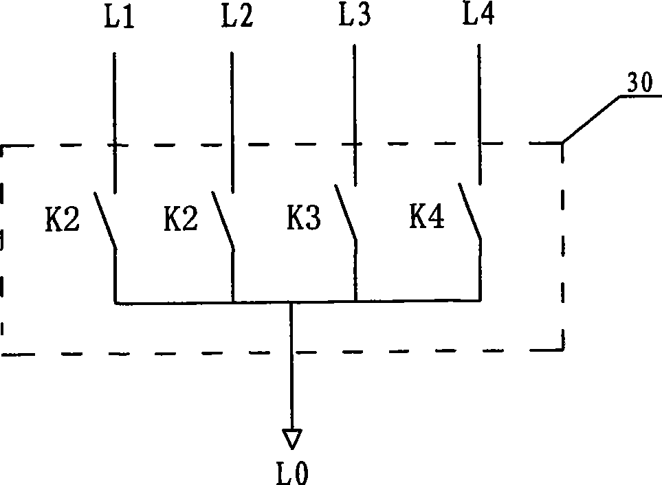
[0022] An interlock transfer switch, comprising N circuit switches, N actuators and a mechanical interlock mechanism, where N is a positive integer.

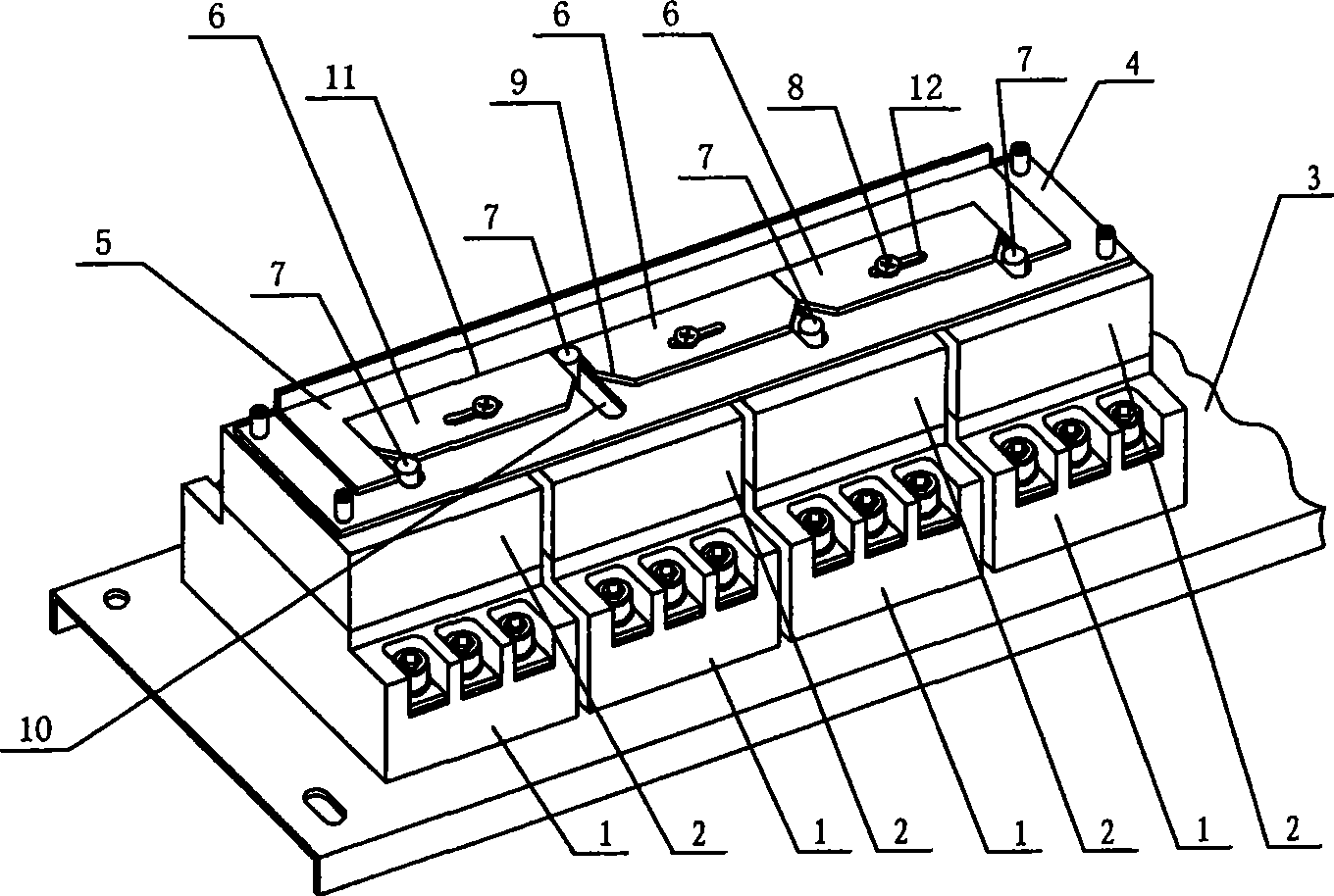
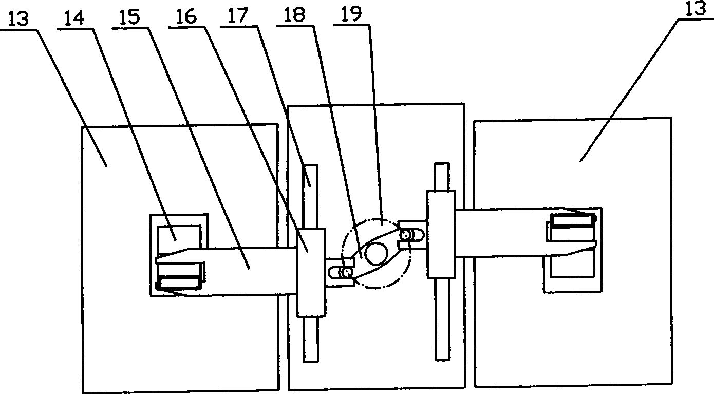
[0023] This embodiment is a four-circuit interlocking changeover switch, and its structure is shown in the attached figure 1 , it consists of 4 circuit switches 1 concentrated and installed horizontally and side by side on the bottom plate 3, each circuit switch 1 is stacked with an actuator 2, and the 4 actuators 2 are connected through a common mechanical interlock mechanism; mechanical interlock The mechanism is composed of three limit blocks 6 that slide left and right in parallel on the guide rail 4. The long plate-shaped guide rail 4 is transversely connected to the panels of the four actuators 2, and the guide rail 4 corresponds to each actuator. 2 There is a longitudinal bar hole...


PUM


Abstract

The invention provides an interlocked changeover switch which comprises N circuit switches and N actuators superposed on the N circuit switches correspondingly, wherein the N circuit switches and the N actuators are in centralized transverse arrangement on a base plate. The N actuators are interconnected via a shared mechanical interlocking mechanism. The mechanical interlocking mechanism comprises a strip-shaped guide rail and (N-1) stoppers arranged inside the II-shaped opening on the guide rail. The guide rail is connected on the panel of the N actuators. Longitudinal elongated holes are formed on the guide rail in the positions corresponding to the shifter rods of the individual actuators, and allow the shifter rods to pass through and shift upwards and downwards. The two ends at the bottom edge of each stopper are chamfered. The width of the II-shaped opening of the guide rail is larger than the sum of width of the (N-1) stoppers, with a difference that is enough to enable the shifter rod of one actuator to shift upwards and downwards. The N is a positive integer. The interlocked changeover switch has the advantages that the interlocked changeover switch can interlock and switch in several power-supply circuits at the same level, with simple structure and convenience for installation and maintenance; simplifies the primary circuit; shortens the power-off time; improves the interlocking reliability; and improves the power supply security.

Description

Technical field: [0001] The invention relates to a circuit changeover switch, in particular to an interlocking changeover switch for more than three power supply circuits. Background technique: [0002] At present, units or equipment that require relatively reliable power supply generally use power grid dual-circuit power supply. And more important units or departments have diesel generator sets, mobile power stations, UPS and other equipment as backups to obtain more reliable power supply protection, so it is necessary to select and convert these three or more power supply circuits. The currently known method is to use a dual power supply automatic conversion device to perform power conversion. What adopts in this device is a double circuit interlocking transfer switch. [0003] The existing technology of using a double-circuit interlocking transfer switch to convert three or more power supply circuits has obvious shortcomings, mainly in: [0004] 1. The existing double-...

Claims


Application Information

Patent Timeline
Patent Type & Authority Applications(China)
IPC IPC(8): H01H9/26
Inventor 陈志霏陈可夫冯浪平陶志林李斌李林
Owner 湖南电器研究所
Why Eureka
Try Eureka