Variable stiffness spoke for a non-pneumatic assembly

A non-pneumatic, spoked technology, used in non-pneumatic tires, vehicle parts, tire parts, etc., can solve problems such as limiting static and vertical deflection, and achieve the effect of reducing stress concentration

Inactive Publication Date: 2009-06-03
MICHELIN & CO CIE GEN DES ESTAB MICHELIN +1
View PDF3 Cites 9 Cited by
  • Summary
  • Abstract
  • Description
  • Claims
  • Application Information

AI Technical Summary

Problems solved by technology

In this case, the high stiffness limits the static vertical deflection

Method used


Image

  • Variable stiffness spoke for a non-pneumatic assembly
  • Variable stiffness spoke for a non-pneumatic assembly
  • Variable stiffness spoke for a non-pneumatic assembly

Examples


Embodiment Construction

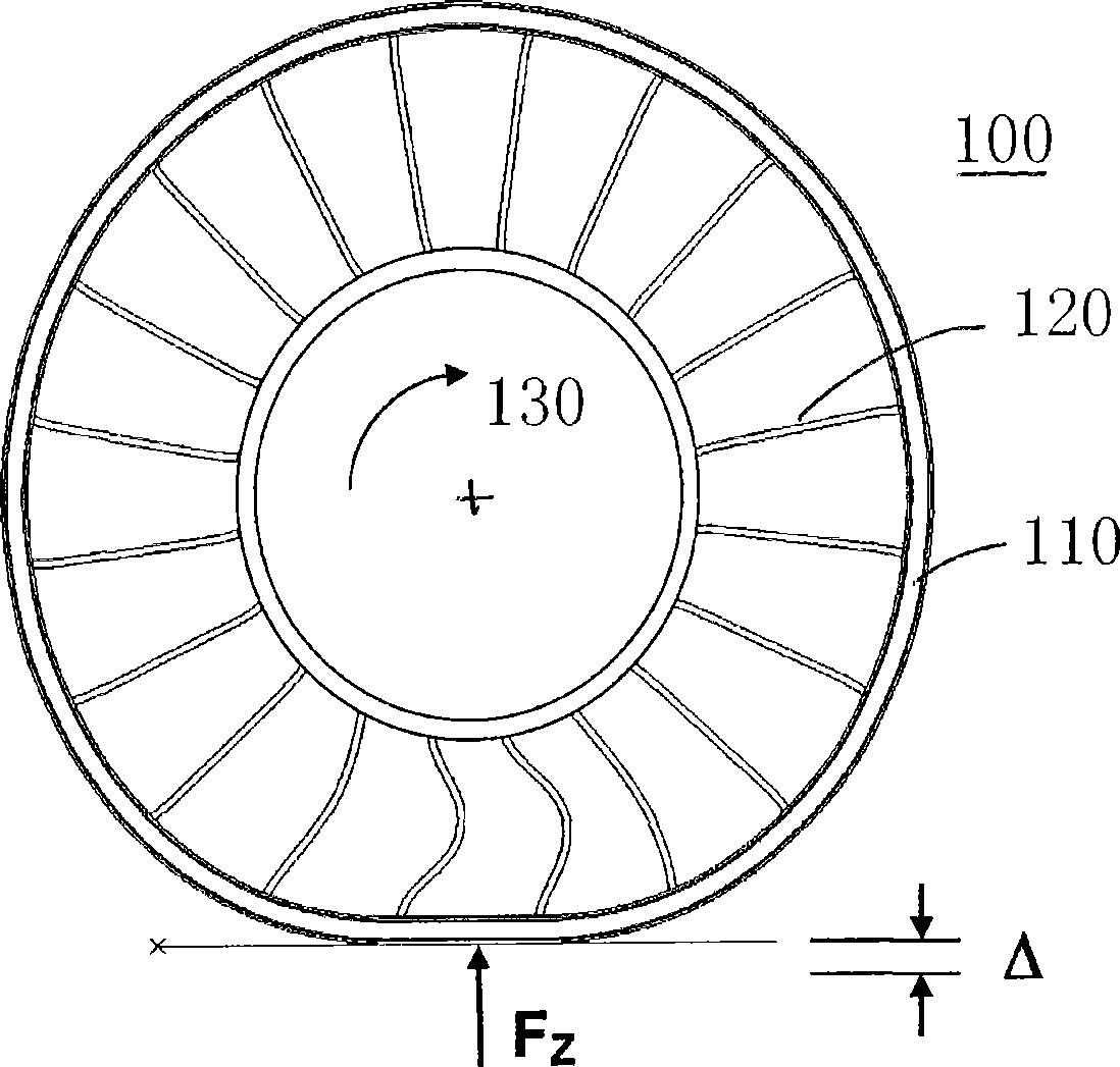
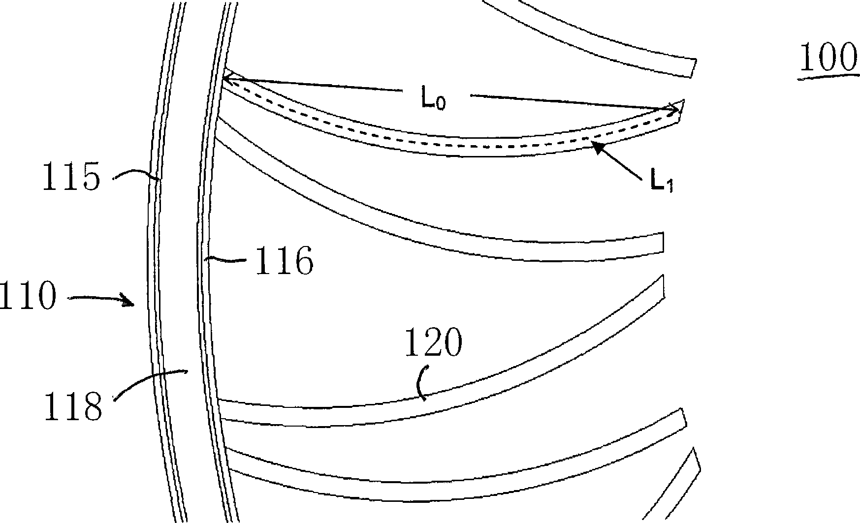
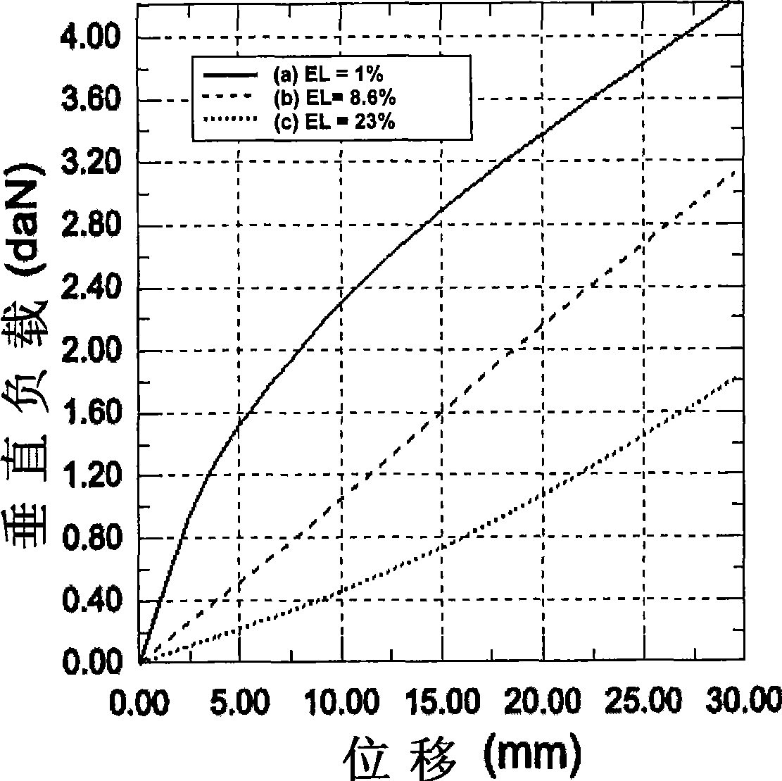
[0021] figure 1 is an example of a non-pneumatic deformable structure 100 . The structure includes an outer band 110 having a predetermined stiffness. A set of spoke-like elements 120 connects the strap 110 to the hub 130 . Hub 130 may then be connected to a vehicle axle or other device capable of rotating about an axis. Rigidity of the belt can be obtained by single or multiple layers of different types of reinforcements. US Patent Nos. 7,013,939 and 6,769,465 provide examples of suitable belt constructions and design information to achieve the required load carrying capacity. figure 1 describes the vertical load F under the condition that the hub 130 is kept immovable in the vertical direction Z Applied to a non-pneumatic structure 100. The portion of the outer belt 110 that is in contact with the ground is subjected to an upward vertical displacement Δ. Figure 3a is the force F for three levels of excess length EL (described below) Z Graphic representation of the re...


PUM


Abstract

The invention described herein provides a non-pneumatic deformable structure having a variable stiffness spoke assembly that provides a method of adjusting the vertical stiffness. The structure comprises an outer annular band having a predetermined stiffness, a set of spoke elements having an outer end and an inner end, where the outer end is connected to the outer band, with the spoke element extending inward and having its inner end connected to a hub, the hub being configured to attach the structure to a vehicle axle or other apparatus capable of rotation about an axis. Each of the spoke elements has a curvilinear length greater than the length of a straight line segment extending from a point of connection of the outer end of the spoke element with the outer annular band to a point of connection of the inner end of the spoke element to the hub. The outer end of said spoke element is tangent to the straight line segment, and the inner end of said spoke element is tangent to the straight line segment.

Description

Background technique [0001] Non-pneumatic deformable structures for use in the support of loads under rolling conditions, such as those supporting motor vehicle loads, have been described, for example, in US Patent No. 7,201,194, commonly owned by the assignee of the present invention. The structurally supported non-pneumatic tire disclosed therein includes a reinforced annular belt to support the load and a plurality of web spokes to transmit the load forces in tension between the annular belt and the wheel or hub. The tire supports its load entirely by structural properties and, contrary to the mechanism in a pneumatic tire, has no support from internal air pressure. [0002] here in figure 1 In the exemplary structure shown in , the spokes are shown as radially oriented elements that then extend more or less across the width of the non-pneumatic deformable structure. The structure being described as a "top load" structure means that a vertical load applied from the ground...

Claims


Application Information

Patent Timeline
Patent Type & Authority Applications(China)
IPC IPC(8): B60B9/26
CPCB60B9/26B60C7/18
Inventor S·M·克龙
Owner MICHELIN & CO CIE GEN DES ESTAB MICHELIN
Why Eureka
Try Eureka