
Identification of base stations

一种基站、识别信号的技术,应用在电气元件、多路复用通信、接入限制等方向,能够解决识别困难增加等问题

Inactive Publication Date: 2009-06-03
LUCENT TECH INC
View PDF0 Cites 2 Cited by
  • Summary
  • Abstract
  • Description
  • Claims
  • Application Information

AI Technical Summary

Problems solved by technology

As the use of indoor cells, mini cells and / or pico cells increases, so do the associated identification difficulties

Method used


Image

  • Identification of base stations
  • Identification of base stations
  • Identification of base stations

Examples


Embodiment Construction

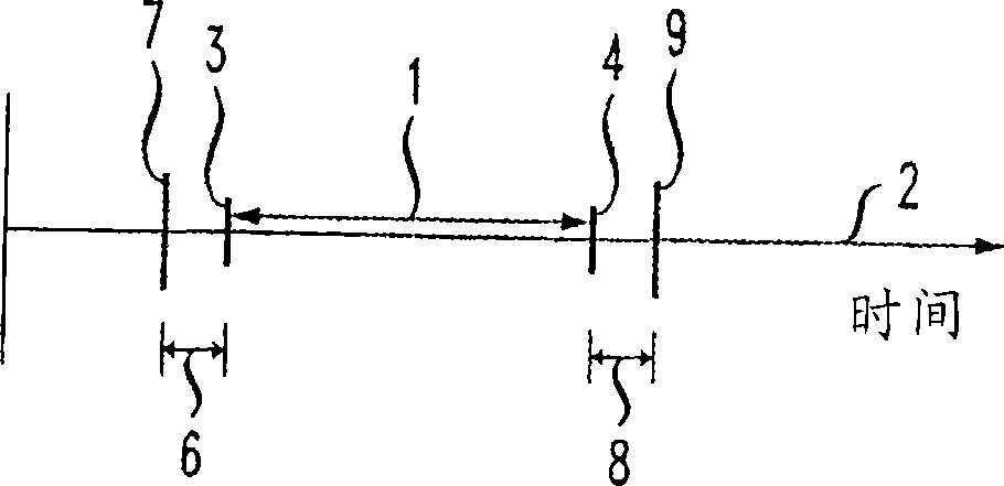
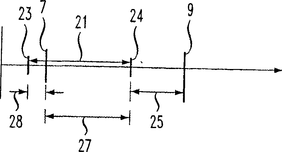
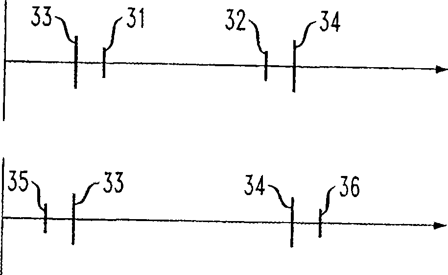
[0015] Identification of base stations in compact cells is achieved using phase shifts related to at least one benchmark, preferably at least two benchmarks, of the beacon signal. (The terms phase shift and phase are used interchangeably in the remainder of this disclosure.) For the purposes of this invention, a reference is a point in time that is identifiable, inter alia, from a repeating transmission pattern. Thus, in the example of a CDMA system, an exemplary reference is the time at which each PN offset begins. For UMTS systems, the exemplary reference is also the start of each data frame. The phase associated with each reference is the point in time associated with each reference at which the pattern of the beacon signal actually begins. To illustrate, the start of a two second time interval is marked by a GPS (global positioning satellite) signal in a CDMA system. As previously discussed, this two-second interval is divided into 75 26-2 / 3 millisecond segments. Each s...


PUM


Abstract

The present invention relates to identification of base stations. The identification of wireless communication base stations in a region of high base station density is effected using a specific identification signal pattern transmitted by the base stations. In particular, each base station transmits a signal having a pattern with at least two time phase shifts relative to at least one time benchmark. The combination of these phase shifts allows identification of the transmitting base station. Since a plurality of phase shifts leads to a concomitantly larger number of phase shift combinations, the capacity to identify base stations is enlarged.

Description

technical field [0001] The present invention relates to wireless communication systems and in particular to wireless communication systems requiring identification of base stations. Background technique [0002] A wireless network is typically divided into cells, where each cell has at least one base station. A user wishing to send information within a cell establishes communication with a base station within the cell. The receiving base station typically communicates with a mobile switching center (MSC), another base station, or another network entity, which in turn relays the information to the center via the network to a central office or to a base station in the cell where the intended recipient is located. [0003] To achieve this goal, several protocols have been developed. A fundamental requirement for any network is the ability for a mobile to identify the base station whose signal it is receiving. Several techniques have been developed to implement the identific...

Claims


Application Information

Patent Timeline
Patent Type & Authority Applications(China)
IPC IPC(8): H04W48/08H04B1/707H04W48/16
CPCH04W48/16H04W48/08H04J13/0029H04B2201/70702H04B1/7083
Inventor Z·马P·A·波拉科斯
Owner LUCENT TECH INC
Learn More