Check patentability & draft patents in minutes with Patsnap Eureka AI!

Electronic apparatus

A technology for electronic equipment and side covers, which is applied to electrical equipment shells/cabinets/drawers, electrical components, thin material processing, etc., can solve the problem that the structure of decorative panels has not been considered, achieve easy installation or removal, and improve aesthetics Effect

Inactive Publication Date: 2009-06-10
MAXELL HLDG LTD
View PDF3 Cites 0 Cited by
  • Summary
  • Abstract
  • Description
  • Claims
  • Application Information

AI Technical Summary

Problems solved by technology

However, in the prior art described above, no consideration has been given to a structure in which each decorative panel can be individually exchanged.

Method used


Image

  • Electronic apparatus
  • Electronic apparatus
  • Electronic apparatus

Examples


Embodiment Construction

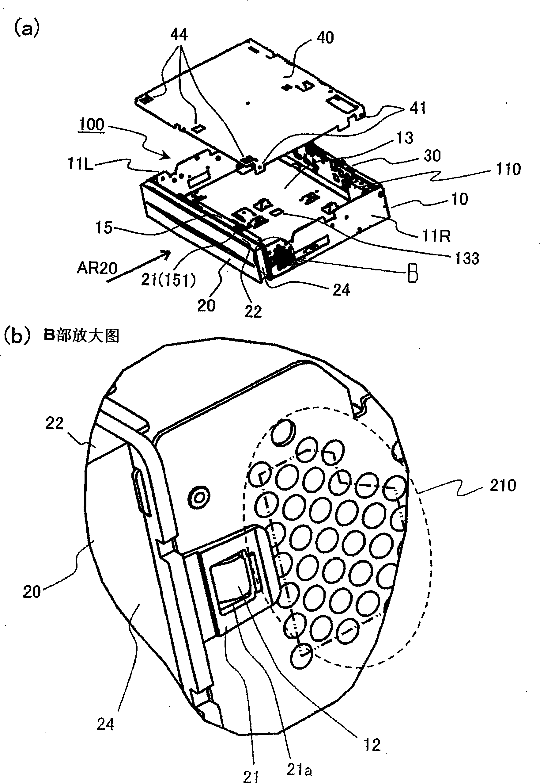
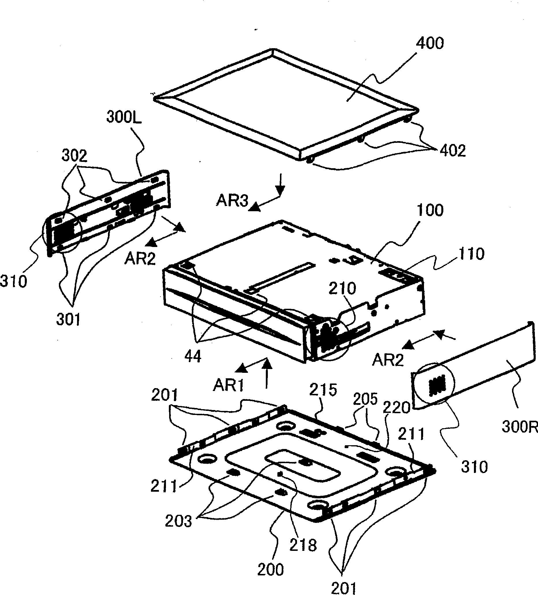
[0080] Hereinafter, preferred embodiments of the present invention will be described with reference to the drawings. Hereinafter, description will be given using a receiving device for receiving television broadcast signals as electronic equipment, but the present invention is not limited thereto. In addition, in each drawing, the same code|symbol is attached|subjected to the component which has the same function, and in order to avoid complexity, the description of the content which has already been demonstrated is not repeated.

[0081] The receiving device as the electronic equipment of the present invention has EMI (Electromagnetic interference: electromagnetic interference) generation sources such as electronic circuit boards or other electronic parts not shown inside, and in order to reduce the EMI caused by it, it is covered with a metal body, so that Shields unwanted radiation (EMI) radiating out of the receiving device. That is, the housing is made of a metal box-sha...


PUM


Abstract

A design cover attachment structure is provided capable of facilitating attachment / removal of a design cover composed of a plurality of decorative plates. At least a top surface and both side surfaces of a generally box-like casing of an electronic apparatus are covered with a design cover composed of a top surface decorative plate, a left side surface decorative plate, and a right side surface decorative plate. The left side surface decorative plate and the right side surface decorative plate are provided with second engagement portions configured to be engaged with first engagement portionsprovided to a bottom surface decorative plate mounted on the casing or a bottom surface of the casing and third engagement portions configured to be engaged with fourth engagement portions provided to the top surface decorative plate. First, the second engagement portions of the left side surface decorative plate and the right side surface decorative plate are engaged with the first engagement portions so that the left side surface decorative plate and the right side surface decorative plate are mounted on the casing. Next, the fourth engagement portions of the top surface decorative plate are engaged with the third engagement portions of the left side surface decorative plate and the right side surface decorative plate so that the top surface decorative plate is mounted on the left side surface decorative plate and the right side surface decorative plate.

Description

technical field [0001] The present invention relates to a technique for installing a decorative cover on an outer surface of a casing of an electronic device. Background technique [0002] Conventionally, when constituting the appearance of an electronic device, a technique of covering the outer surface of the electronic device with a decorative cover is known. For example, as described in Patent Document 1, in order to reduce the man-hours of assembly, the top cover is slid from the rear, so that the hooks provided on both sides of the top cover are engaged with the hooks provided on the two sides of the base corresponding to the hooks. on the snap hole. On the contrary, there is another example, for example, as described in Patent Document 2, hooks are provided on both sides of the base, and engagement holes corresponding to the hooks are provided on both sides of the top cover. In addition, as described in Patent Document 3, there is also a technique of covering at leas...

Claims


Application Information

Patent Timeline
IPC IPC(8): H05K5/00H05K5/03
CPCH05K5/0013Y10T428/13Y10T428/1355Y10T428/1352Y10T428/1397
Inventor 岸祐司塚本乾堀川善宪西晋司岸和摩森岛彰俊
Owner MAXELL HLDG LTD
Features
  • R&D
  • Intellectual Property
  • Life Sciences
  • Materials
  • Tech Scout
  • Unparalleled Data Quality
  • Higher Quality Content
  • 60% Fewer Hallucinations
Learn More