Anti-theft lock

A technology of locks and lock bases, which is applied in building locks, buildings, building structures, etc., can solve the problem of low anti-theft performance and achieve strong anti-theft effects

Inactive Publication Date: 2009-06-17
朱阿静
View PDF5 Cites 1 Cited by
  • Summary
  • Abstract
  • Description
  • Claims
  • Application Information

AI Technical Summary

Problems solved by technology

But the lockset of this structure has a fatal shortcoming: promptly when adopting external force to forcibly rotate lock cylinder, can rotate lock cylinder easily, and drive described rotary block to rotate, make lock bolt relatively move, to fall off. The gap of the hook can easily open the lock, so although it has the function of automatic locking, its anti-theft performance is not high

Method used


Image

  • Anti-theft lock
  • Anti-theft lock
  • Anti-theft lock

Examples


Embodiment Construction

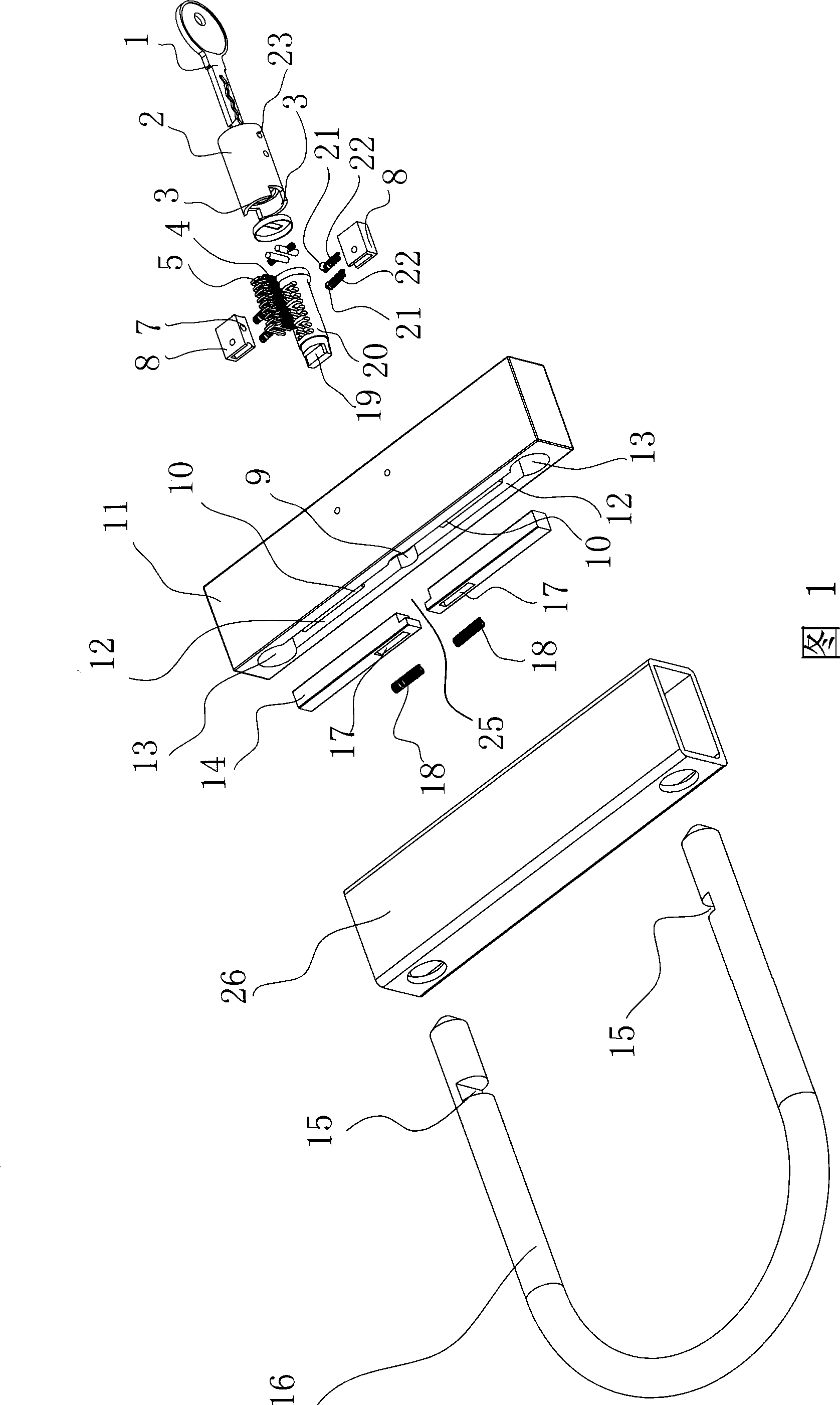
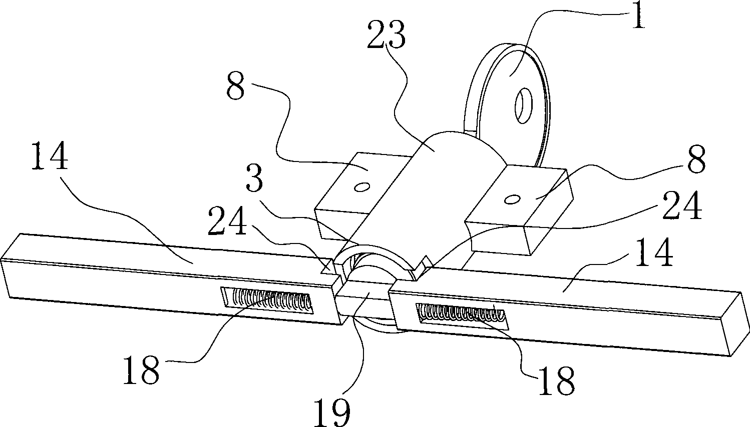
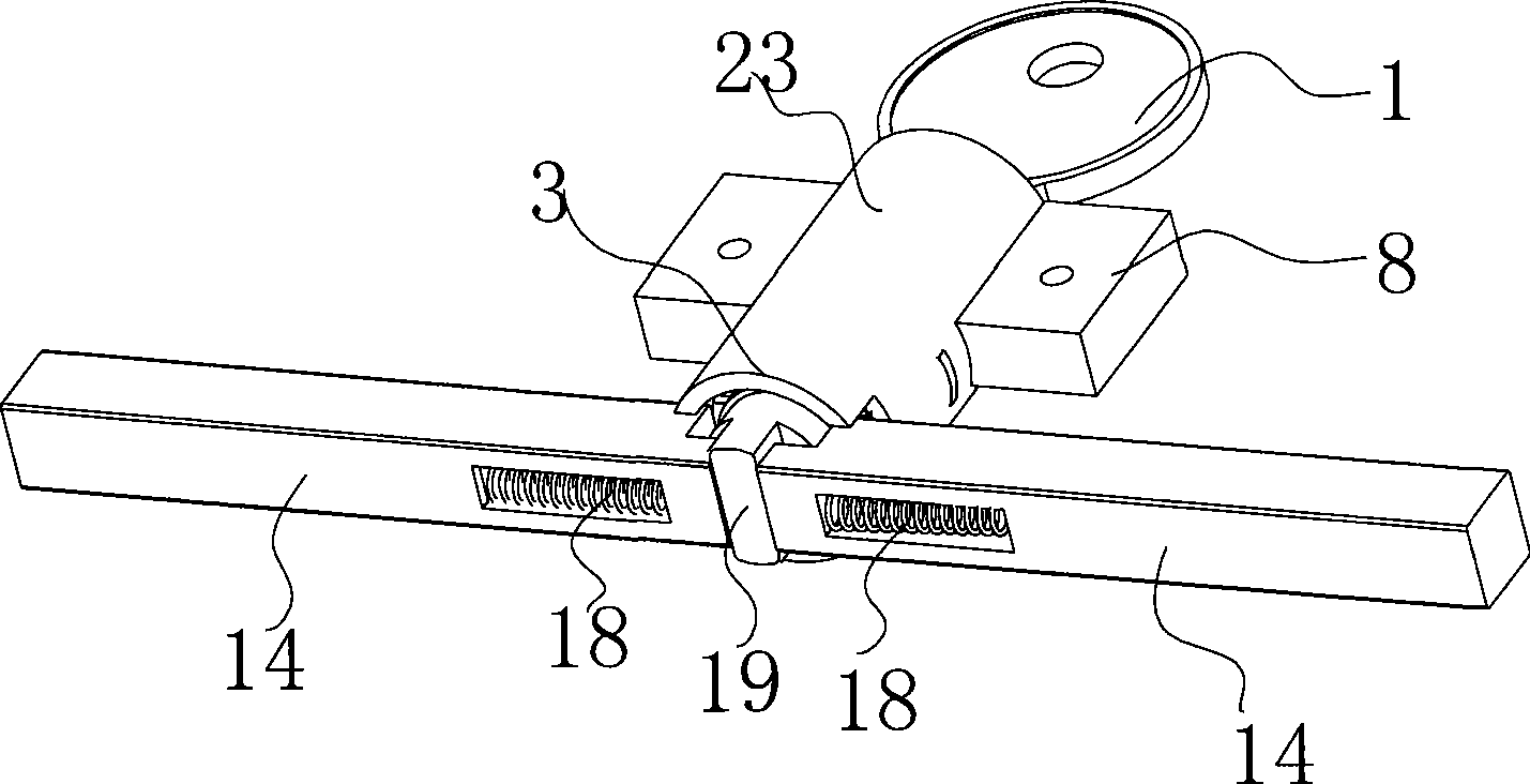
[0011] With reference to accompanying drawing, this anti-theft lockset comprises U-shaped lock bar 16, lock base 11, lock core 20 and lock core shell 2, and described lock base 11 is installed in lock base shell 26, and described U-shaped lock bar 16 its Both ends form gaps 15, the lock cylinder 20 is sleeved in the lock cylinder shell 2, the lock cylinder 20 has a flat bolt 19, the lock base 11 has a lock cylinder installation hole 9, and the lock The core shell 2 is placed in the lock cylinder installation hole 9, and the lock base 11 has a U-shaped lock rod 16 socket 13, and the two sides of the lock cylinder installation hole 9 on the lock base 11 are provided with grooves 12, and the groove 12 A lock bolt 14 is installed in the groove 12, and the flat bolt 19 is placed between the two lock bolts 14. A top seat 10 is arranged in the groove 12, and the lock bolt 14 has a function A groove body (not shown) for accommodating the top seat 10, the lock bolt 14 is provided with ...


PUM


Abstract

The invention discloses an anti-theft lockset, which is mainly characterized in that lock plungers (14) are arranged at two sides of a lock core mounting hole (9) of a base (11), a tabular lock tongue (19) is arranged between the two lock plungers, the lock plunger contacts a footstock (10) inside the lock base by a lock plunger spring (18), projecting parts (3) are arranged symmetrically on a lock core shell (2) in axial direction, steps (24) are arranged at the ends opposite to the lock plungers at the two sides of the lock core mounting hole (9), the two steps form a faucet (25), when the lock core shell (2) is installed inside the lock core mounting hole, the projecting part of the lock core shell (2) is positioned outside the faucet formed by the two steps. Regarding the anti-theft lockset of the structure, when a lock is opened by force, the projecting part on the lock core shell thereof locks the lock plunger, the lock can not be opened no matter how strong a force is, the anti-theft lockset has strong anti-theft performance and extremely suits lock of motor vehicles, factory gates and the like.

Description

technical field [0001] The invention relates to a hardware product, in particular to an anti-theft lockset with a U-shaped lock bar. Background technique [0002] At present, the lockset structure of general motor vehicles or factory doors is mostly a U-shaped lock rod interspersed with the tires of the motor vehicle or the factory door handle, and then inserted and fastened with a lock seat, and then locked by the lock seat. The structure closes the opening of the U-shaped lock bar, so that the U-shaped lock bar is inserted into the tire or the door handle, so as to achieve the purpose of locking the motor vehicle or the door. Check the Chinese patent database, and get an authorized announcement number of CN2467708Y, the invention name is "automatic lockable motorcycle lock", which discloses the following content: the automatic lockable motorcycle lock, including: a lock seat, forming a pair of hoops The hook socket, and the latch channel that runs through the hoop hook so...

Claims


Application Information

Patent Timeline
IPC IPC(8): E05B65/00E05B63/14
Inventor 朱阿静
Owner 朱阿静
Why Eureka
Try Eureka