

Chain capable of reducing weight
A technology for reducing weight and chains, applied in the field of chains, can solve problems such as easy deflection, inability to spread uniformly, unstable riveting quality, etc., and achieve the effect of expanding area and reducing weight
- Summary
- Abstract
- Description
- Claims
- Application Information
AI Technical Summary
Problems solved by technology
Method used
Image

Examples
Embodiment Construction
[0020] The aforementioned and other technical contents, features and functions of the present invention will be clearly presented in the following detailed description of preferred embodiments with reference to the drawings.
[0021] Before the present invention is described in detail, it should be noted that in the following description, similar elements are denoted by the same reference numerals
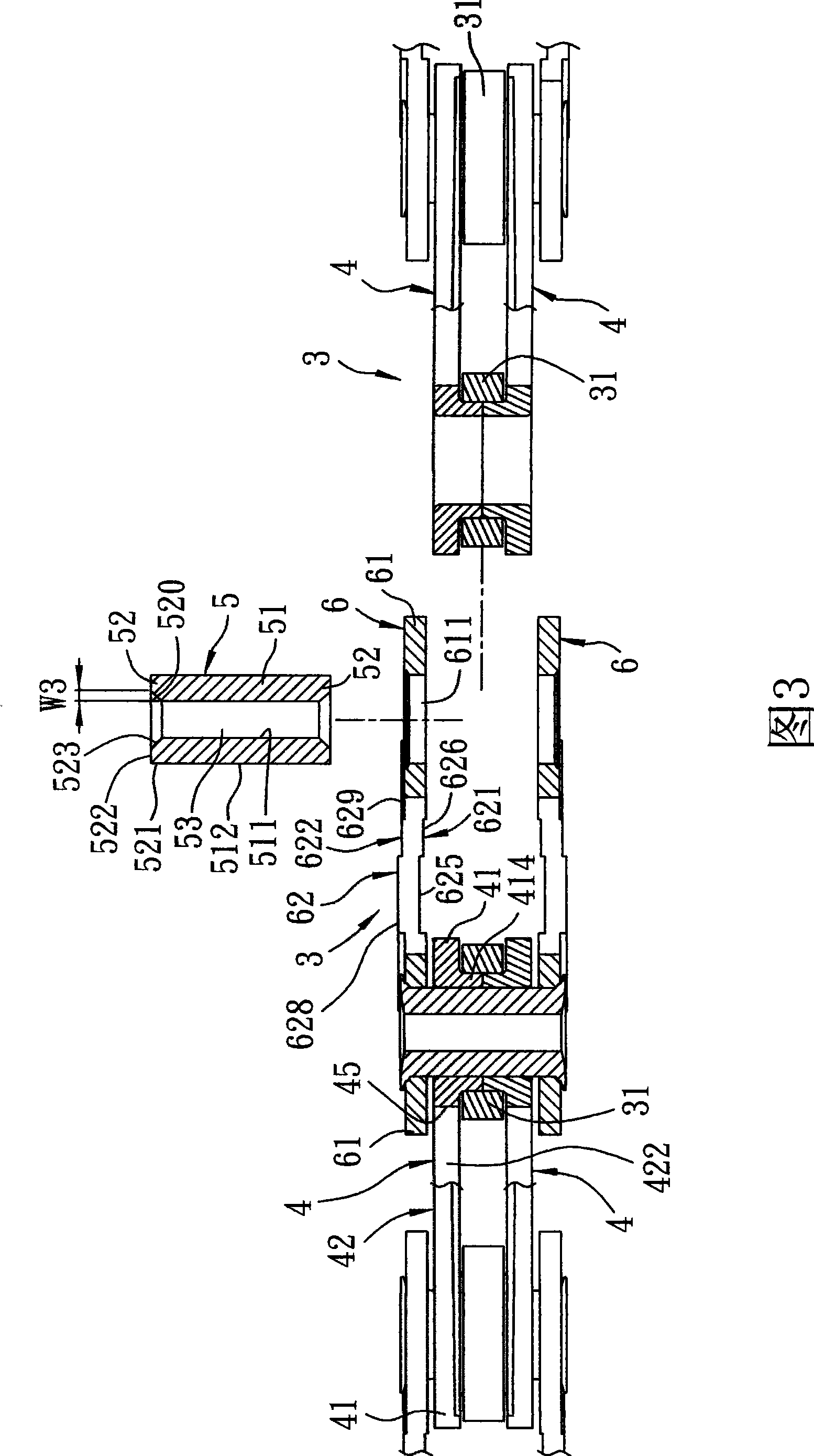
[0022] Referring to Fig. 3, 4, 5, the first preferred embodiment of the chain of the present invention comprises: several serial connection units 3 arranged left and right. Each tandem unit 3 includes: two first chain pieces 4 that are parallel inside and outside, two chain rollers 31 that are rotatably positioned between these first chain pieces 4, and two first chains that are respectively positioned on the same side. The second chain piece 6 outside the piece 4 and partially overlapped, and two chain shafts 5 connecting the adjacent first and second chain pieces 4, 6 in series. ...
PUM
| Property | Measurement | Unit |
|---|---|---|
| Width | aaaaa | aaaaa |
| Radius | aaaaa | aaaaa |
Abstract
Description
Claims
Application Information