
Assembly method for principal shaft and gearbox of large aerogenerator

A wind turbine and assembly method technology, applied in the assembly of wind turbines, wind turbine components, wind turbines, etc., can solve the problems of reduced assembly work efficiency, high risk of overturning, increased risk, etc., to achieve the benefit of mass production The production and assembly process is simple and the use time is shortened

Active Publication Date: 2009-06-24
GUANGDONG MINGYANG WIND POWER IND GRP CO LTD
View PDF0 Cites 23 Cited by
  • Summary
  • Abstract
  • Description
  • Claims
  • Application Information

AI Technical Summary

Problems solved by technology

The disadvantages of this assembly method are: 1. The gearbox is large in size and weighs more than ten tons, making it difficult and dangerous to turn over
The hydraulic wrench weighs more than ten kilograms, so the operator is prone to fatigue, which greatly reduces the efficiency of assembly and is prone to accidents
3. Since the assembly height after assembly is 5 to 6 meters, the weight is as high as nearly 30 tons
It is too difficult to flip, the efficiency is too low, and the risk is great
4. Due to the high height of the assembly parts, the requirements for the lifting height of the assembly workshop are also high
5. Due to the need to flip parts multiple times, the relatively long time spent on the crane is not conducive to mass production
6. Since the assembly point is above 2 meters high, a platform needs to be installed, and workers need to work at heights, which increases the danger of work

Method used


Image

  • Assembly method for principal shaft and gearbox of large aerogenerator
  • Assembly method for principal shaft and gearbox of large aerogenerator
  • Assembly method for principal shaft and gearbox of large aerogenerator

Examples


Embodiment Construction

[0019] Below in conjunction with accompanying drawing and specific embodiment the present invention is described in further detail:

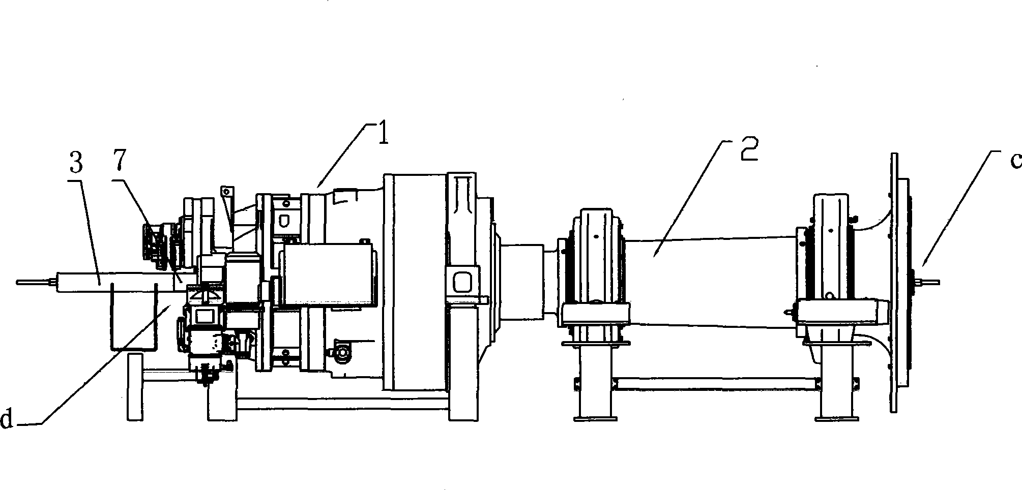
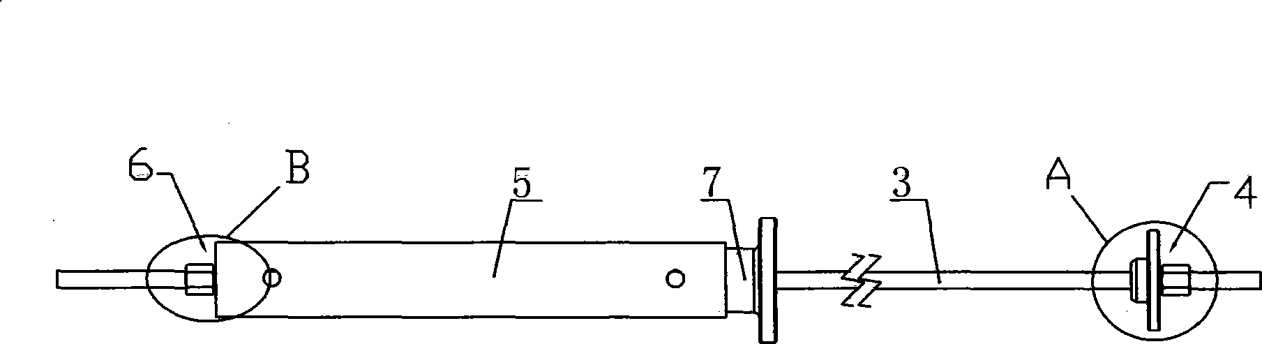
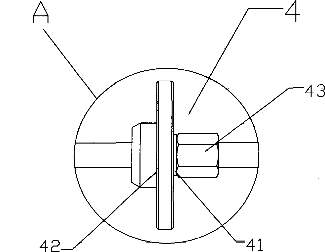
[0020] A method for assembling a main shaft and a gearbox of a large-scale wind power generator, such as figure 1 , 2 As shown, the assembly steps are as follows:

[0021] a. First place the gear box 1 horizontally on the gear box rack to ensure that the main shaft hole of the gear box is basically level. The gear box 1 is provided with a hole that penetrates the gear box opposite to the main shaft hole so that the pull rod 3 behind can be Pass through both ends of the gear box 1; b. Lift the hollow main shaft 2 horizontally with a sling, and align the connection with the gear box 1 with the installation position of the gear box; c. Adjust the height and left and right positions of the crown block to make the main shaft 2 and the gear box The shaft hole of the main shaft is coaxial; d. Use a pull rod 3 to pass through the hole of the main shaf...


PUM


Abstract

The invention relates to a method for assembling a main shaft and a gear box of a large-scale wind-driven generator. The assembly steps are as follows: a. the gear box is horizontally arranged on a rack to cause the shaft hole of the main shaft of the gear box to be horizontal, and a hole which relatively penetrates the shaft hole of the main shaft is arranged on the gear box; b. the main shaft is horizontally lifted to target at the installation position of the gear box; c. an overhead travelling crane is adjusted to cause the main shaft to be coaxial with the shaft hole of the gear box; d. a pull rod penetrates the hole of the main shaft and the hole on the shaft center of the gear box, and a fixed block member is underlaid under one end of the pull rod extending out from the main shaft; e. the other end of the pull rod, which extends out from the gear box, is sheathed with a jack, and is provided with a fixing member; f. the jack is driven to extend, and on the premise that both ends of the pull rod are fixed, the extension of the jack can pull the main shaft into the gear box; g. after being pulled into the gear box, the main shaft is fixed on the gear box by a locking ring; h. the main shaft is well supported by the support, and hanging belts are removed; and i. the fixing member and the jack are dismounted, the pull rod is pulled out of the main shaft and the gear box, and finally, the entire assembly process is completed.

Description

【Technical field】 [0001] The invention relates to a method for assembling a main shaft of a large-scale wind power generator and a gear box, and is mainly suitable for assembling a main shaft of a large wind power generator with a non-direct drive structure and a gear box. 【Background technique】 [0002] When the existing large-scale wind turbines are assembled with the main shaft and the gearbox, they all adopt the vertical assembly method, that is, the main shaft is turned upside down first, and then the connection part of the gearbox is placed upwards on the platform, and then the gearbox is placed on the platform. Flip over so that the connecting part of the gearbox is perpendicular to the connecting part of the main shaft, lift the gearbox and place it on the main shaft and ensure that it is concentric with the main shaft, and then slowly drop it so that the connecting part of the gearbox and the main shaft are inserted into the connecting hole spindle. After assemblin...

Claims


Application Information

Patent Timeline
IPC IPC(8): F03D11/04F03D13/10
CPCY02E10/728Y02E10/72
Inventor 陈平华
Owner GUANGDONG MINGYANG WIND POWER IND GRP CO LTD
Features
  • Generate Ideas
  • Intellectual Property
  • Life Sciences
  • Materials
  • Tech Scout
  • Unparalleled Data Quality
  • Higher Quality Content
  • 60% Fewer Hallucinations
Learn More