Curve lens detection system

A detection system and lens technology, applied in measuring devices, material analysis through optical means, instruments, etc., can solve problems such as uneven light irradiation, improve accuracy and avoid detection blind spots

Inactive Publication Date: 2009-06-24
UTECHZONE CO LTD
View PDF0 Cites 10 Cited by
  • Summary
  • Abstract
  • Description
  • Claims
  • Application Information

AI Technical Summary

Problems solved by technology

[0004] However, because the existing curved lens inspection system 1 uses backlighting to illuminate the curved lens 12, and the light source 11 is usually a long tubular fluorescent lamp, the light irradiation is prone to unevenness, resulting in blind spots in the inspection.

Method used


Image

  • Curve lens detection system
  • Curve lens detection system
  • Curve lens detection system

Examples


Embodiment Construction

[0013] The foregoing and other technical contents, features and effects of the present invention will be clearly presented in the following detailed description of the two preferred embodiments with reference to the accompanying drawings.

[0014] Before the present invention is described in detail, it should be noted that in the following description, similar elements are denoted by the same reference numerals.

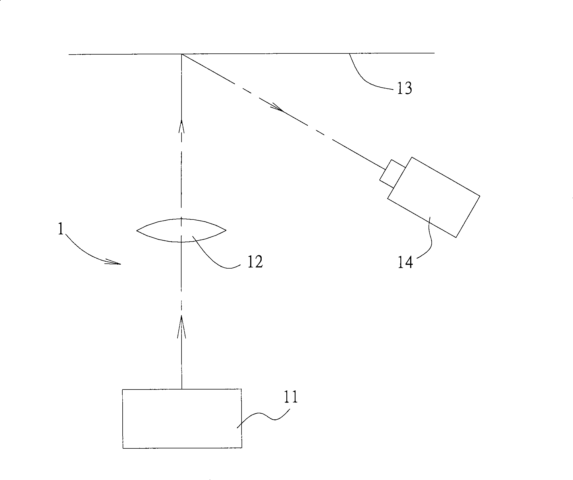
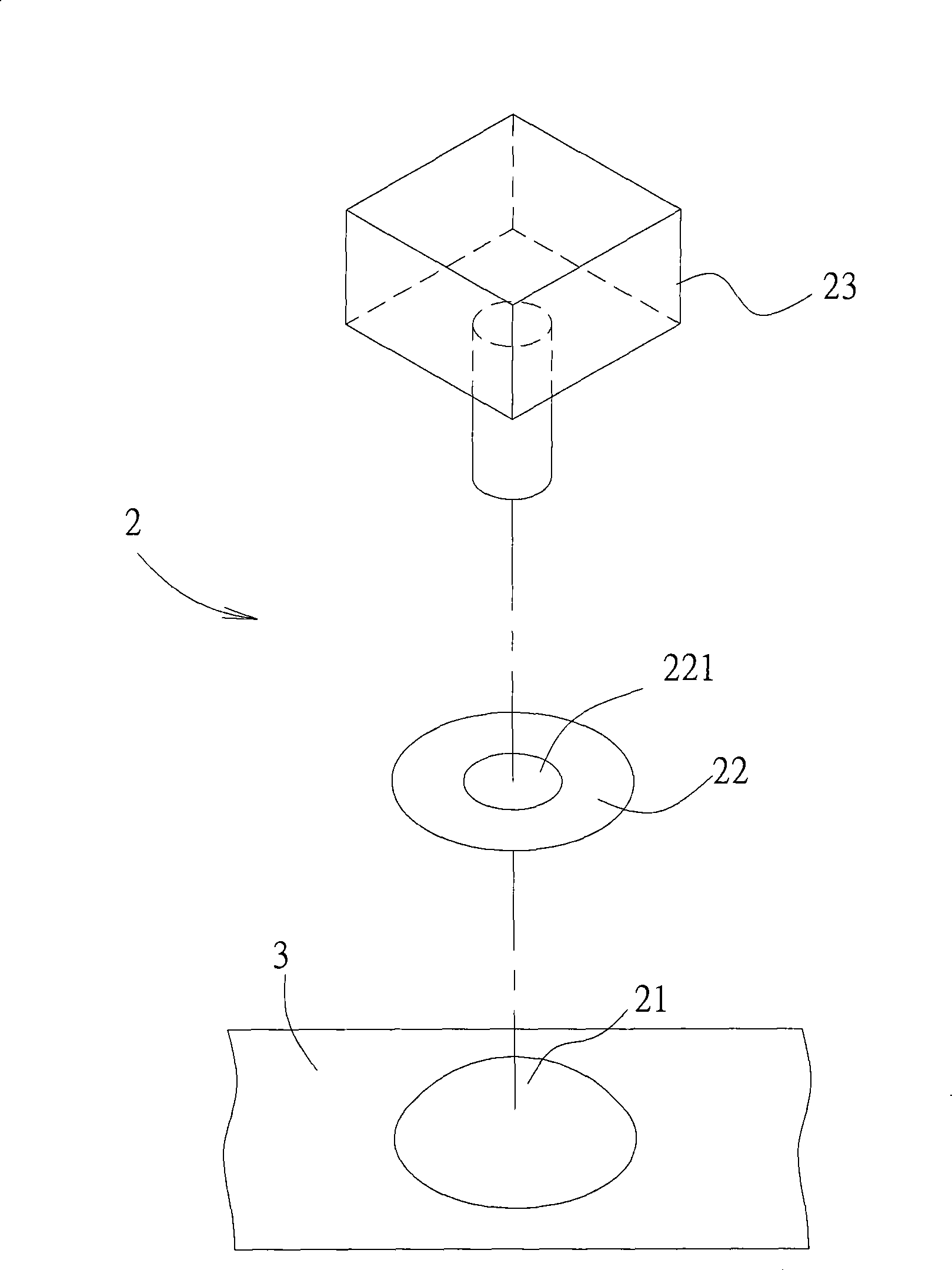
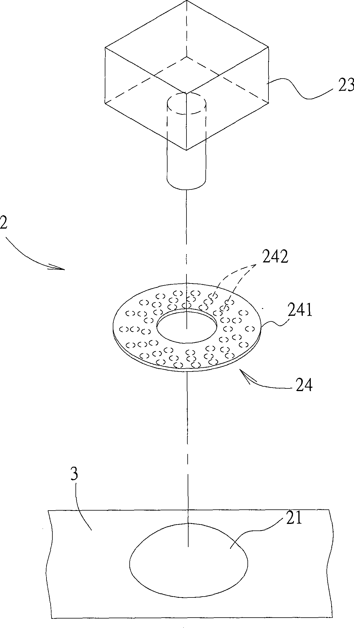
[0015] refer to figure 2 , to illustrate the first preferred embodiment of the curved lens inspection system of the present invention. The curved lens detection system 2 includes a ring light source device 22 arranged above a curved lens 21 to be tested, and an image capture device 23 arranged above the ring light source device 22, that is, the curved lens 21, the ring The installation positions of the light source device 22 and the image capture device 23 are located on the same straight line. Furthermore, the curved lens 21 to be tested is placed on a stage 3 . ...


PUM


Abstract

The invention relates to a system for detecting a curved surface lens, which comprises a ring-shaped light source device arranged above the curved surface lens, and an image acquisition device arranged above the ring-shaped light source device; the ring-shaped light source device is provided with an opening, through which the image acquisition device can acquire an image of the curved surface lens; and therefore, by the production of uniform light by the ring-shaped light source device at the opening and the projection of the light onto the curved surface lens to be tested, the detection accuracy can be enhanced.

Description

technical field [0001] The invention relates to a curved lens detection system, in particular to a curved lens detection system capable of improving detection accuracy. Background technique [0002] Ordinary curved lenses, including concave and convex spherical lenses or aspheric lenses, must be inspected for defects such as scratches, dirt, white spots, and white fog after the production is completed to ensure the quality of the lenses. [0003] Such as figure 1 As shown, it is a common curved surface lens inspection system 1, which mainly installs the light source 11 at the position below a curved surface lens 12 to be tested, and uses the lighting method of the backlight to project the image of the curved surface lens 12 on a screen ( screen) 13, the image capture device 14 placed on the side captures the image of the curved lens 12 illuminated by the light source 11 on the screen 13, so that when the curved lens 12 is defective, the image will show different light and s...

Claims


Application Information

Patent Timeline
Patent Type & Authority Applications(China)
IPC IPC(8): G01N21/958
Inventor 李世光郑振纬邱彦博
Owner UTECHZONE CO LTD
Why Eureka
Try Eureka