
Display and electronic apparatus

A display and display circuit technology, applied to static indicators, instruments, electrical digital data processing, etc., can solve the problems of difficult size reduction and high cost, and achieve the effect of improving S/N and reducing the influence of noise

Inactive Publication Date: 2009-06-24
JAPAN DISPLAY INC
View PDF6 Cites 5 Cited by
  • Summary
  • Abstract
  • Description
  • Claims
  • Application Information

AI Technical Summary

Problems solved by technology

[0006] However, a display device provided with such a coordinate input function as described above is difficult to downsize and costs more than ordinary display devices

Method used


Image

  • Display and electronic apparatus
  • Display and electronic apparatus
  • Display and electronic apparatus

Examples


Embodiment Construction

[0059] Now, embodiments of the present invention will be described below with reference to the drawings.

[0060] Hereinafter, first, for ease of understanding, a basic configuration and function of a liquid crystal image display having a light receiving element per display pixel will be described, and then an embodiment related to a specific structure will be described.

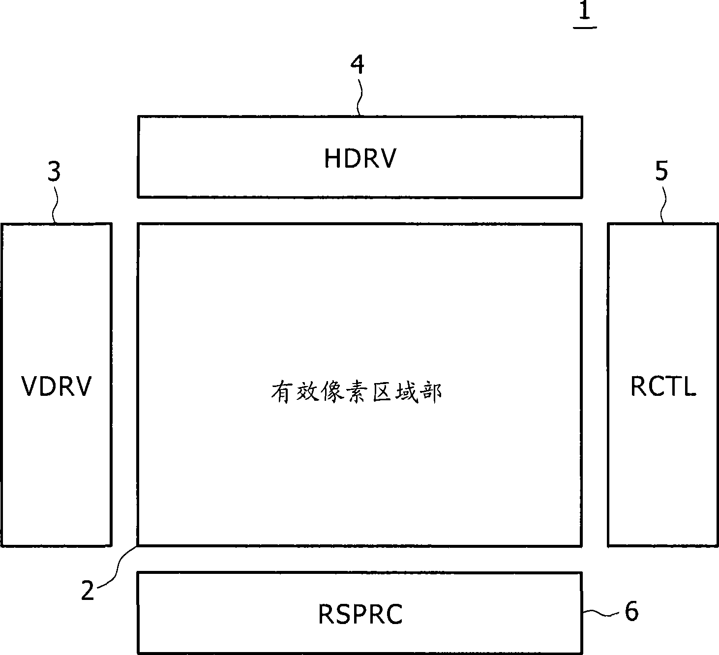
[0061] figure 1 is a block diagram showing a configuration example of a liquid crystal display according to one embodiment of the present invention.

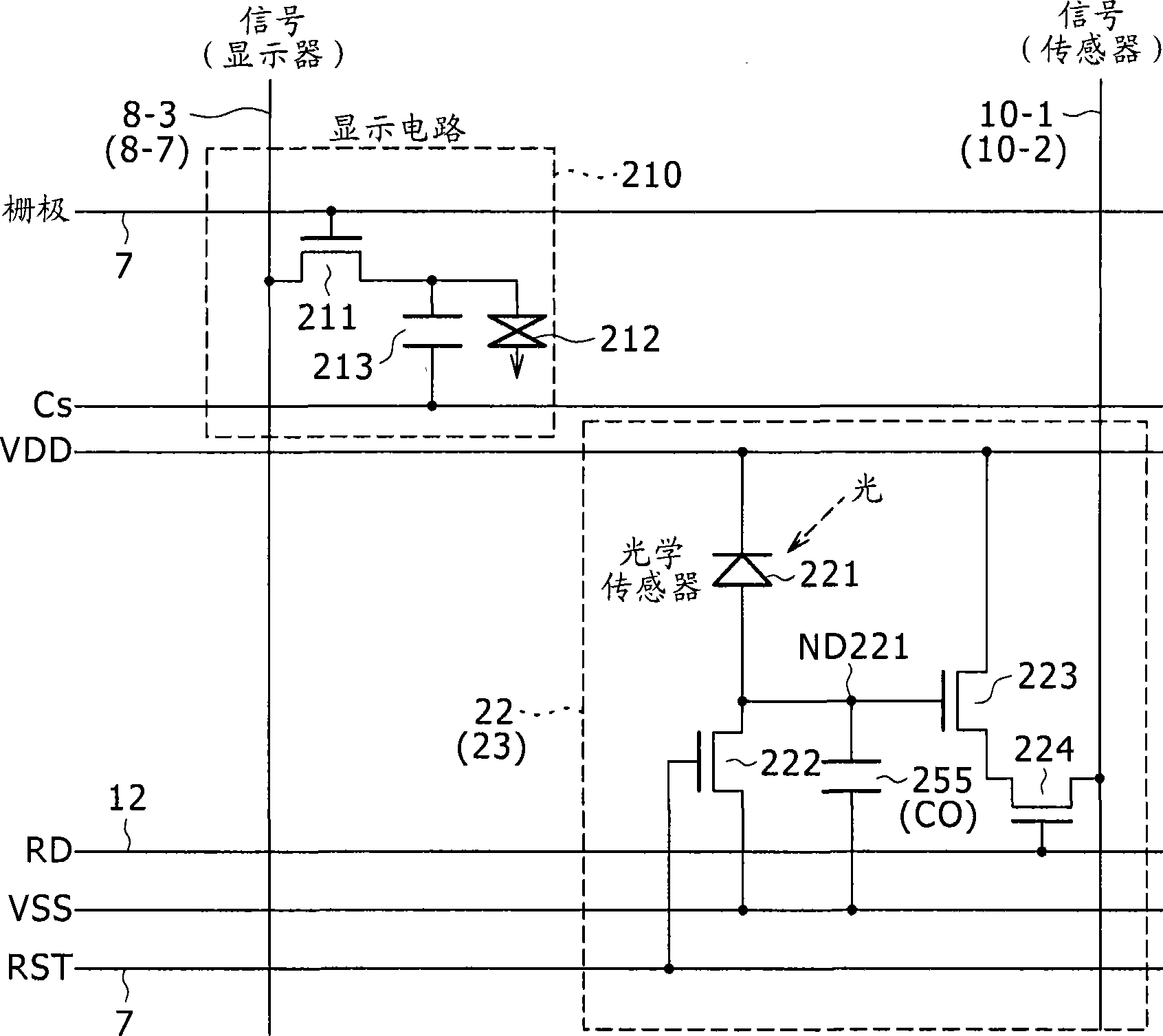
[0062] figure 2 is a circuit diagram showing a basic configuration example of a display unit and a light receiving unit according to the present embodiment. figure 2 In , the display unit and the light receiving unit appear to be adjacent.

[0063] Such as figure 1 As shown, the liquid crystal image display 1 includes an effective pixel region 2 , a vertical drive circuit (VDRV) 3 , a horizontal drive circuit (HDRV) 4 , a light reception control circuit ...


PUM

PropertyMeasurementUnit
refractive indexaaaaaaaaaa

Abstract

A display is provided. The display includes at least one display cell having a display circuit; at least one light receiving cell including a light receiving element; a light emitting section operative to radiate light to the side of a display surface; and a polarizing plate disposed on the front side in the display relative to a region in which the light emitting section is disposed and regions in which the display cell and the light receiving cell are formed, wherein a phase difference plate is disposed at a position which is on the front side relative to the light receiving cell and in either of an emitting optical path of the light emitting section and a reflecting optical path toward the light receiving cell.

Description

[0001] Cross References to Related Applications [0002] The present invention contains subject matter related to Japanese Patent Application JP 2007-326176 filed in the Japan Patent Office on December 18, 2007, the entire content of which is hereby incorporated by reference. technical field [0003] The present invention relates to a display provided with a light emitting element in a display pixel portion or on an architrave-like frame thereof. Background technique [0004] Several technologies of a display device itself provided with a coordinate input function have been proposed. [0005] Specifically, for example, a display device of a pressure-sensitive type touch panel system (see Japanese Patent Laid-Open Nos. 2002-149085 and 2002-41244), a display device of an electromagnetic induction type touch panel system (see Japanese Patent Laid-Open No. Hei 11) are known. -134105) etc. [0006] However, a display device provided with such a coordinate input function as desc...

Claims


Application Information

Patent Timeline
Patent Type & Authority Applications(China)
IPC IPC(8): G02F1/1335G02F1/133G06F3/041
CPCG02F1/13338G02F2001/13312G06F3/0421G06F3/0416G06F3/0412G02F1/13312G02F1/1335G02F1/13363
Inventor 高间大辅川副裕之
Owner JAPAN DISPLAY INC
Learn More