Radiating device

A technology of heat dissipation device and heat pipe, which is applied in the direction of cooling/ventilation/heating transformation, electrical components, electric solid devices, etc., can solve the problems of increased manufacturing cost of radiators, and achieve the effect of overall manufacturing cost control and overall manufacturing cost

Inactive Publication Date: 2009-06-24
FU ZHUN PRECISION IND SHENZHEN +1
View PDF0 Cites 0 Cited by
  • Summary
  • Abstract
  • Description
  • Claims
  • Application Information

AI Technical Summary

Problems solved by technology

However, one fixture can only be used for one kind of radiator. If the size of the radiator changes, it is necessary to redesign and manufacture a fixture of the corresponding size, resulting in an increase in the overall manufacturing cost of the radiator.

Method used


Image

  • Radiating device
  • Radiating device
  • Radiating device

Examples


Embodiment Construction

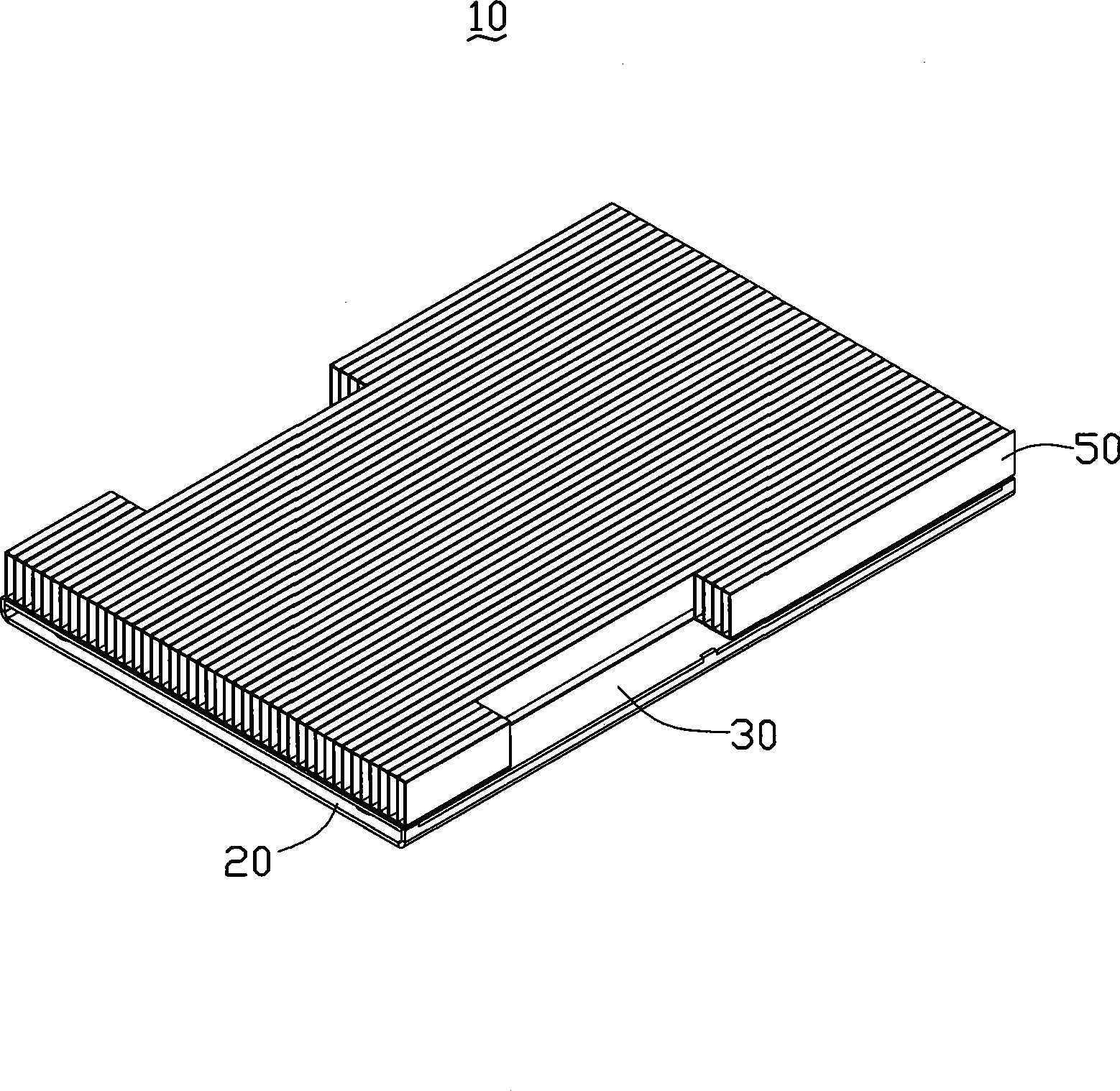
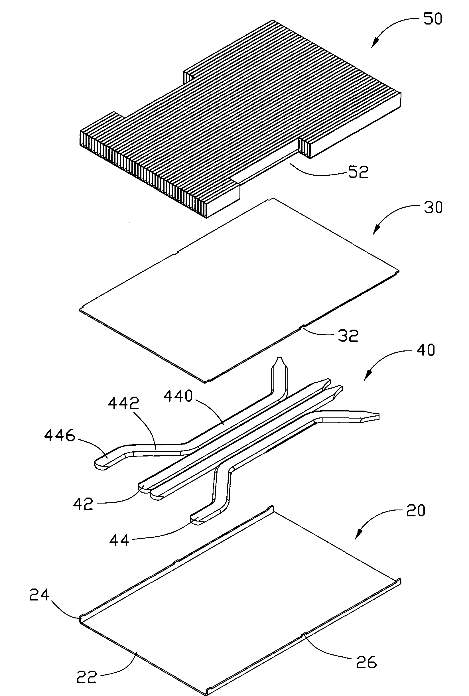
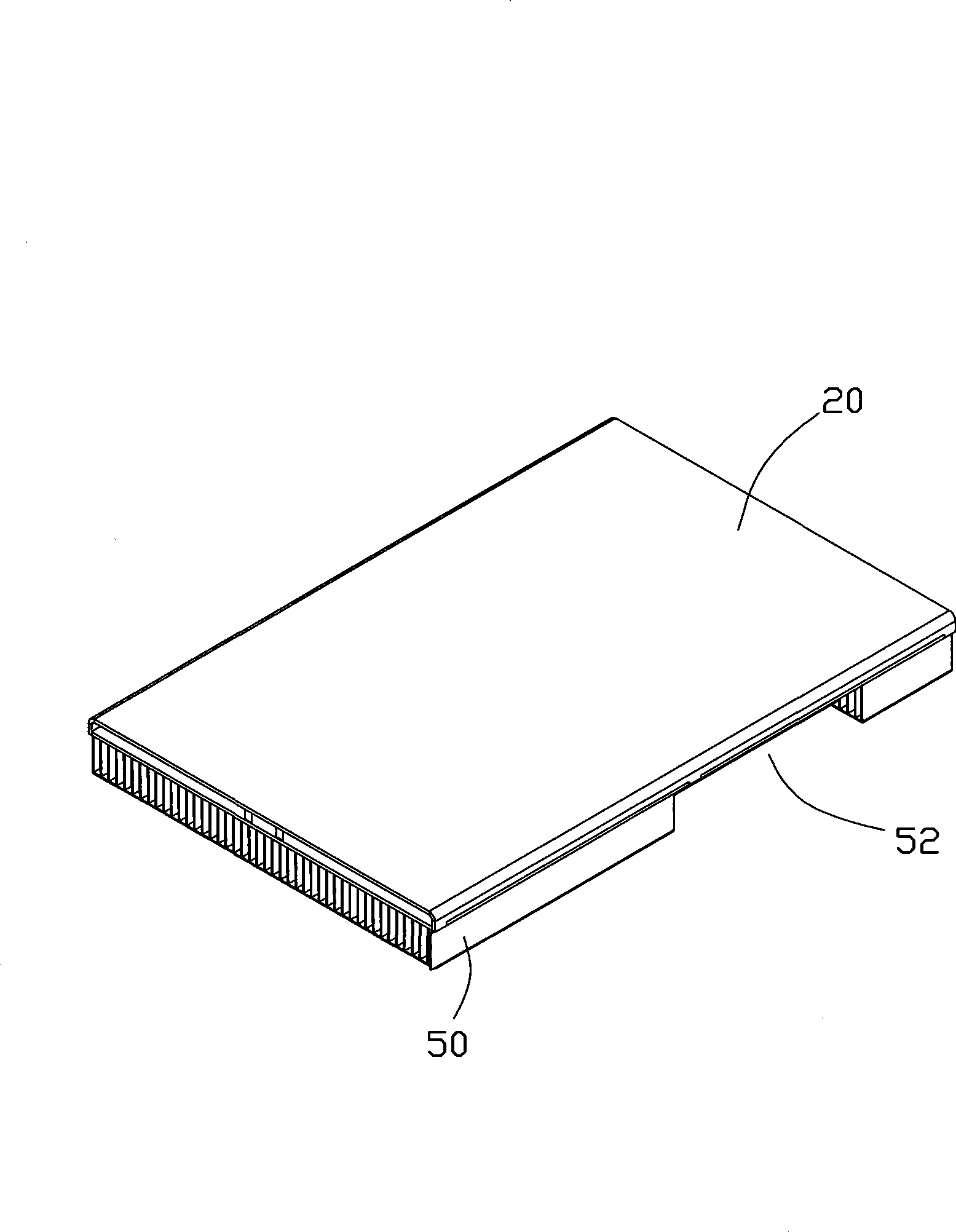
[0014] Such as figure 1 and 2 As shown, the heat dissipation device 10 of the present invention is used to dissipate heat from electronic components (not shown) mounted on a circuit board (not shown), and includes a base plate 20, a top plate 30 mounted on the base plate 20, a combination To the fin group 50 on the top plate 30 and a plurality of plate-shaped heat pipes 40 sandwiched between the bottom plate 20 and the top plate 30 .

[0015] Please also refer to Figure 4 , the bottom plate 20 is integrally formed by a metal plate, which is in contact with the electronic components to absorb the heat generated by the electronic components. The longitudinal section of the bottom plate 20 is roughly "U"-shaped, and it includes a flat rectangular plate body 22, two side walls 24 extending vertically upward from opposite sides of the plate body 22, and a plurality of rectangular plates respectively formed on the side walls 24. Positioning piece 26. Each side wall 24 is rectan...


PUM


Abstract

The invention relates to a heat radiator used for heat dissipation of electronic components, comprising a base plate, a top plate and a plurality of heat pipes, wherein, the top plate is arranged on the based plate and the heat pipes are clamped between the top plate and the base plate. The base plate comprises a plate body carrying the heat pipes and side walls extending upwards from the two opposite sides of the plate body; and a plurality of locating plates which are inserted in the top plate are arranged on the side walls. Compared with the prior art, the locating plates are arranged on the side walls of the base plate of the heat radiator, and the locating plates are clamped in the top plate for locating the top plate; therefore, the base plate can realize the locating function for the top plate without needing any locating jig, so as to well control the overall manufacturing cost of the heat radiator.

Description

technical field [0001] The invention relates to a heat dissipation device, in particular to a heat dissipation device for dissipating heat from electronic components. Background technique [0002] In recent years, with the development of the electronics industry, the performance of electronic components has been continuously improved, and the calculation speed has become faster and faster. The calculation speed of the internal chipset has been continuously improved, the number of chips has continued to increase, and the heat emitted by the chips has also increased accordingly. If If the heat is not dissipated in time, the performance of the electronic components will be greatly affected, and the computing speed of the electronic components will be reduced. As the heat continues to accumulate, the electronic components may be burned, so the electronic components must be dissipated. [0003] A traditional radiator includes a bottom plate, a top plate fixed to the bottom plate,...

Claims


Application Information

Patent Timeline
IPC IPC(8): H05K7/20H01L23/40
Inventor 赖其渊周志勇赖振田
Owner FU ZHUN PRECISION IND SHENZHEN
Why Eureka
Try Eureka