Geared driving gear of power branch having rotation input changing into prodeterming rotation output

A gear mechanism and power distribution technology, which is applied in the transmission of mechanical power, engines, engine functions, etc., can solve the problems of large assembly size, uneven load distribution, and expensive lifting equipment required for disassembly, and achieve the best manufacturing cost , the effect of optimal replacement parts cost

Inactive Publication Date: 2008-07-23
SIEMENS AG
View PDF3 Cites 0 Cited by
  • Summary
  • Abstract
  • Description
  • Claims
  • Application Information

AI Technical Summary

Problems solved by technology

[0003] For higher levels of power output, the known gear drives are too complex and heavy, and are subject to large deformations due to the high torque or torsional moment combined with considerable structural dimensions, and resulting from such deformations. produce uneven load distribution
These known gear drive structures have large assembly dimensions
Furthermore, especially when performing maintenance on such gear-driven structures on the bench of a rotary power unit, the toothless parts or bearings of the planetary gear structure may be exchanged
In particular for landing gear the dismantling of the entire gear drive structure or of large assemblies of such a gear drive structure requires relatively expensive lifting equipment
Another disadvantage is that with the increase of the gear drive structure and the 4-pole generator in the 60HZ standard, this gear drive device also becomes more bulky, so that for higher speeds and not exceeding those specified by the bearing manufacturer In the case of the specified maximum speed per minute, it is difficult to use commonly used bearings to achieve a sufficiently long bearing operating life

Method used


Image

  • Geared driving gear of power branch having rotation input changing into prodeterming rotation output
  • Geared driving gear of power branch having rotation input changing into prodeterming rotation output
  • Geared driving gear of power branch having rotation input changing into prodeterming rotation output

Examples


Embodiment Construction

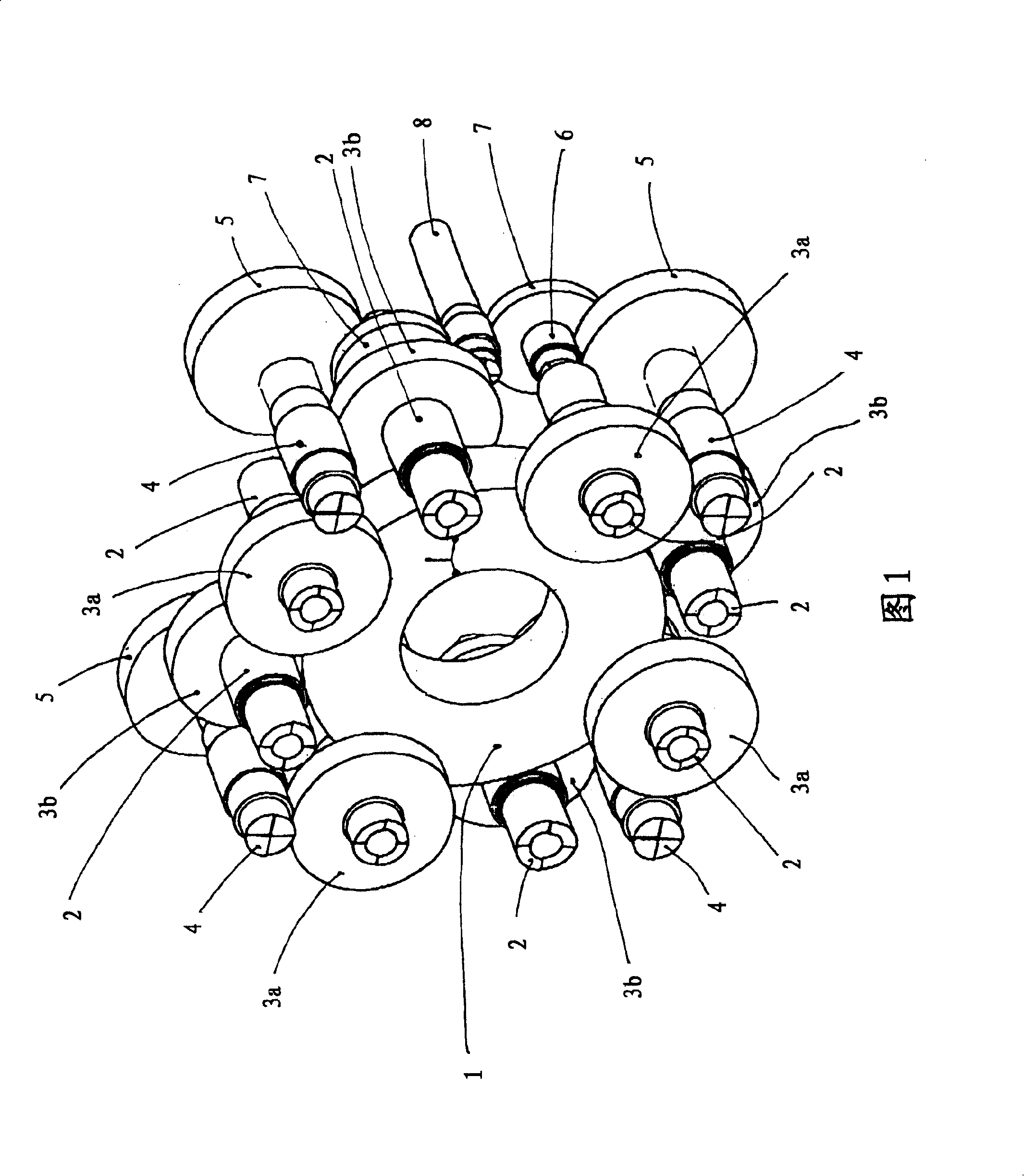
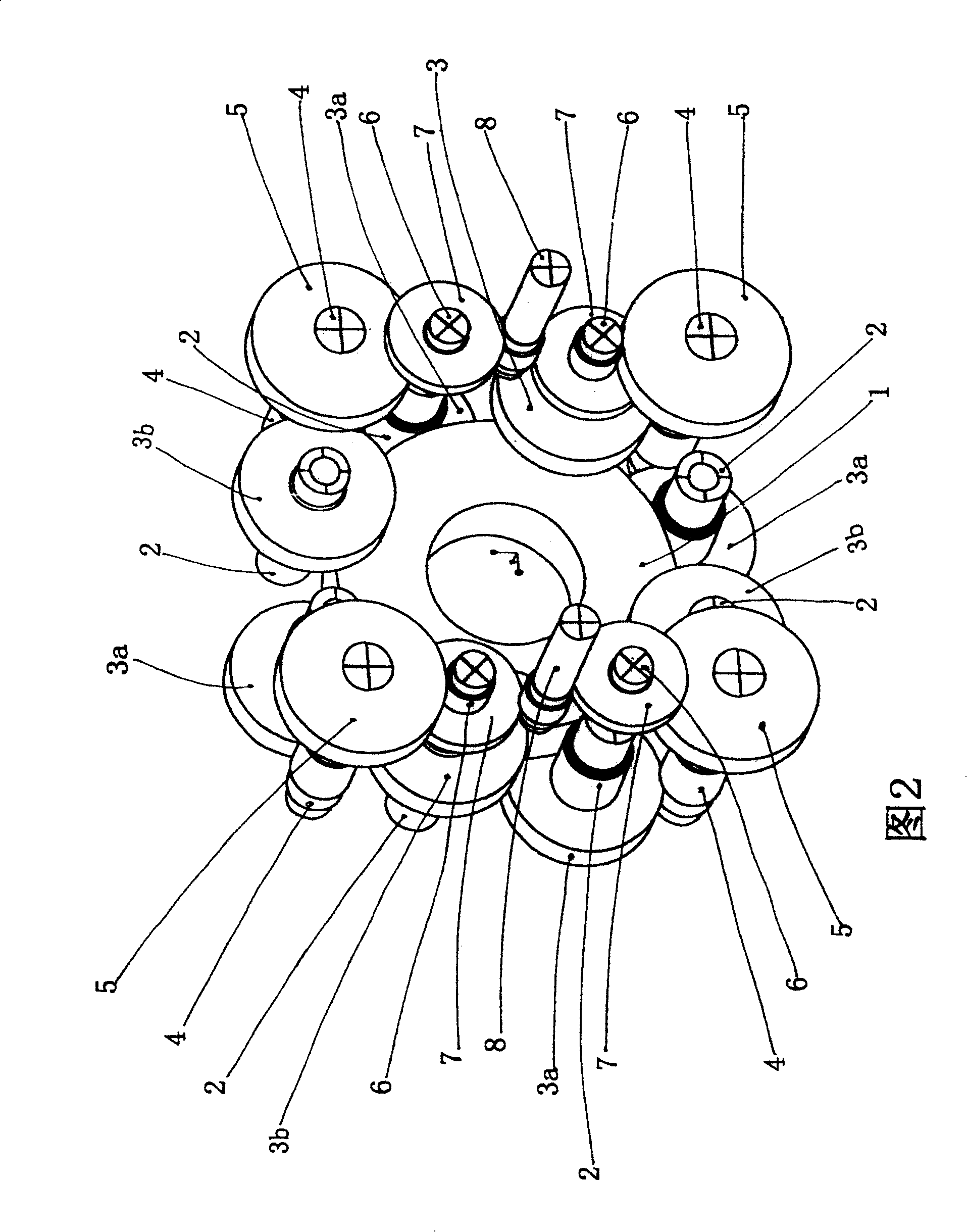
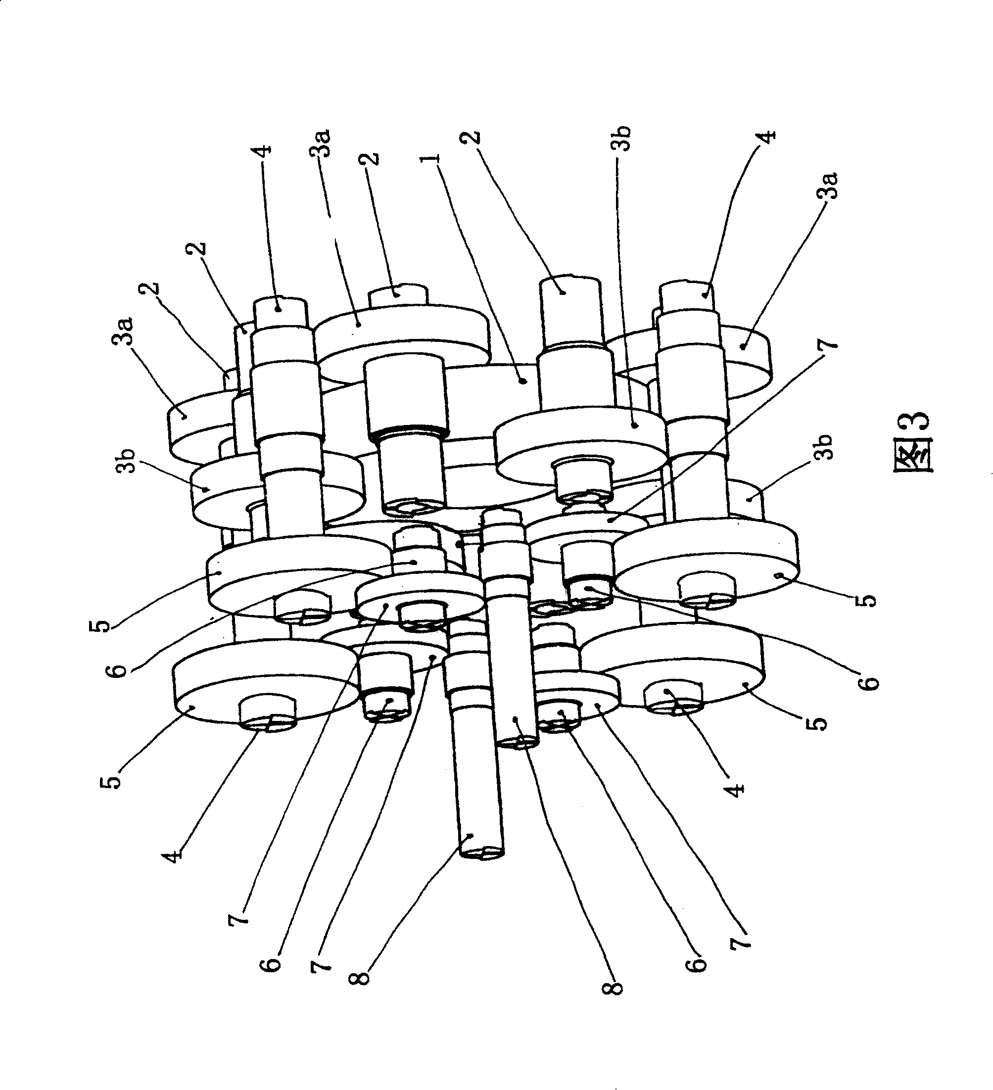
[0029] One embodiment of the gear drive shown in Figures 1-6 is configured as an additional gear drive that augments or augments the rotational output of the rotary power plant by, for example, rotationally driving two generators, said The two generators are driven by the rotor of the rotary power unit, and the gear drive shown in Figure 1-6 is arranged on the table of the rotary power unit between the rotor and the generator. The gear drive comprises a bull gear 1 having gear teeth along its outer circumference. The bull gear 1 is fixedly mounted on a hollow shaft which is supported on bearings at two places inside the gearbox which encloses the gear drive, and the bull gear 1 is coupled to a rotating input shaft which is the rotating power unit. on the rotor shaft.

[0030] Eight pinion shafts 2 are arranged symmetrically around the bull gear 1 , and the pinion gears of the pinion shafts 2 mesh with the bull gear 1 . The bearings of the pinion shaft 2 are arranged in two o...


PUM


Abstract

A gear drive apparatus for converting a rotational input provided by a drive device, such as a wind power generator rotor, into a predetermined rotational output for driving rotation of a driven device, such as a generator, includes a large gear coupled to the drive device and a pair of output pinion shafts coupled to the driven device. A first gear level includes eight primary level pinion shafts each having gear teeth meshingly engaged with the outer circumferential gear teeth of the first large gear. The eight primary level gear or pinions are coaxially secured to the eight primary level pinion shafts for driving rotation thereof. Four secondary level gears and four secondary level pinion shafts form a secondary gear level which rotates the pair of output pinion shafts.

Description

technical field [0001] The invention relates to a gear drive having a power branch for converting a rotational input into a predetermined rotational output. Background technique [0002] Additional or supplementary gear units with internal power branch are known, said power branch is a planetary structure or a kind of axially freely adjustable gear with herringbone structure, moreover, the gear unit also comprises in particular a input shaft and an output shaft. Among other purposes, the rotor of the rotating power structure drives a generator in response to a rotational input using such an additional gear unit, usually connected to the rotor shaft by a press-fit coupling. In this common configuration, the center of the press fit coupling is usually part of the planet gear support and is located within the gearbox. The planetary gears rotating around the planetary gear carrier mesh with the internal teeth of the gears fixed on the gearbox. These planetary gears mesh with a...

Claims


Application Information

Patent Timeline
Patent Type & Authority Patents(China)
IPC IPC(8): F16H1/28F16H1/22F16H37/06
CPCY02E10/722F16H37/065F03D11/02F16H1/22F05B2260/40311F03D15/00Y10T74/19651Y10T74/19079Y10T74/19628F03D80/70F03D15/10Y02E10/72F16H1/28
Inventor 弗朗斯·胡尔绍夫
Owner SIEMENS AG
Why Eureka
Try Eureka