
Lifting assembly for elevating components to a wind turbine and a method for using the lifting assembly

a technology for wind turbines and components, which is applied in the manufacture of wind turbines, machines/engines, wind motor assemblies, etc., can solve the problems of affecting the operation of wind turbines, affecting the transportation of components, and affecting the quality of wind turbines, so as to facilitate the transportation of components

Active Publication Date: 2020-12-15
SKYREX AB
View PDF27 Cites 0 Cited by
  • Summary
  • Abstract
  • Description
  • Claims
  • Application Information

AI Technical Summary

Benefits of technology

This patent describes a way to disassemble and transport a wind turbine tower using buoyant platforms and cranes. The tower is made up of multiple segments that can be connected together to adjust its height and make it easier to transport. The use of multiple segments reduces the need for extra transportation measures, and each segment can be made at a low height to minimize the impact on vehicles delivering the segment. Once all but the last segment is removed, the platform is moved to the support frame, and the last segment can be easily disconnected and moved to the ground, making the disassembly process complete. Overall, this method reduces the amount of transport vehicles needed and makes the process more efficient.

Problems solved by technology

However, these components are often large and heavy, which poses an issue during both the assembly and the maintenance of the wind turbines.
One of the problems with these cranes is that they are highly sensitive to wind, and cannot operate while the wind velocity exceeds certain limits, since the crane becomes too unstable and the wire might start to swing.
This can result in stoppage of production for long periods of time, decreasing the profitability of the wind turbines.
Additionally, the large size and weight of the cranes most commonly used today cause problems with transportation and assembly of the cranes.
A large amount of vehicles are required today to transport the different parts of the cranes, and once the transportation is completed, the assembly of these parts takes a very long time to finish.
All the problems mentioned above cause the assembly and the maintenance of the wind turbines to become expensive and time consuming.
However, a problem with this invention is that it does not account for the instability of the crane's wire, meaning it is still sensitive to high winds.
Another disadvantage is that the crane residing on the main support mast is large and heavy, increasing the overall size and weight of the invention.
This is particularly important when the platform is being moved upwards or downward along the tower, since an unbalanced platform will cause wear on the drive mechanism for moving the platform.
An unbalanced platform may cause the driving mechanism to fail or to become worn out.
This is particularly important when the platform is being moved along the tower, since an unbalanced platform will cause wear on the drive unit.
A crane smaller than 10 tons might not be able to lift necessary objects, e.g. the components of the wind turbine and segments of the tower.
This both saves time and decreases the amount of transport vehicles needed.
If the platform would not be mechanically connected to the tower, but only being held up by the drive unit, the drive unit would be worn out faster due to the large forces the drive unit would be subjected to because of the imbalanced weight.
When using cranes most commonly used today, the new component needs to be collected from the ground, meaning long and wind sensitive wires are required.

Method used


Image

  • Lifting assembly for elevating components to a wind turbine and a method for using the lifting assembly
  • Lifting assembly for elevating components to a wind turbine and a method for using the lifting assembly
  • Lifting assembly for elevating components to a wind turbine and a method for using the lifting assembly

Examples


Embodiment Construction

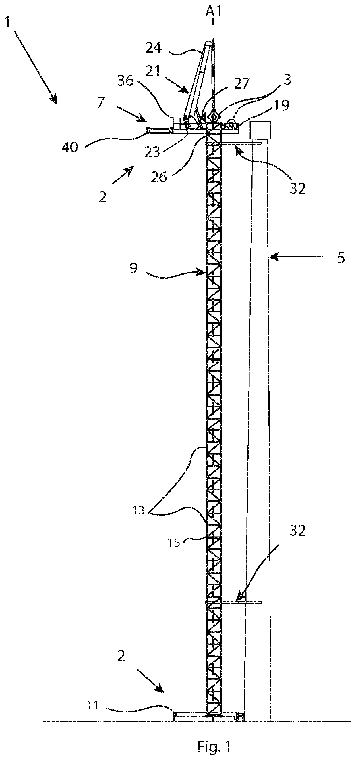
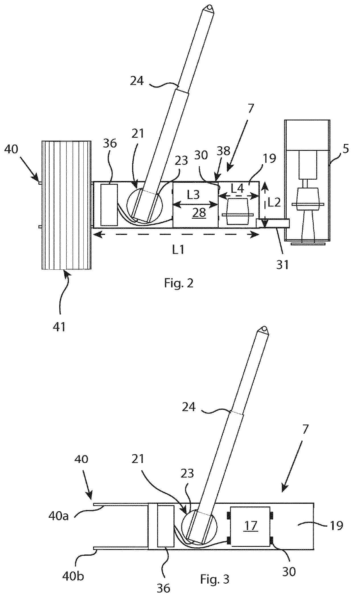
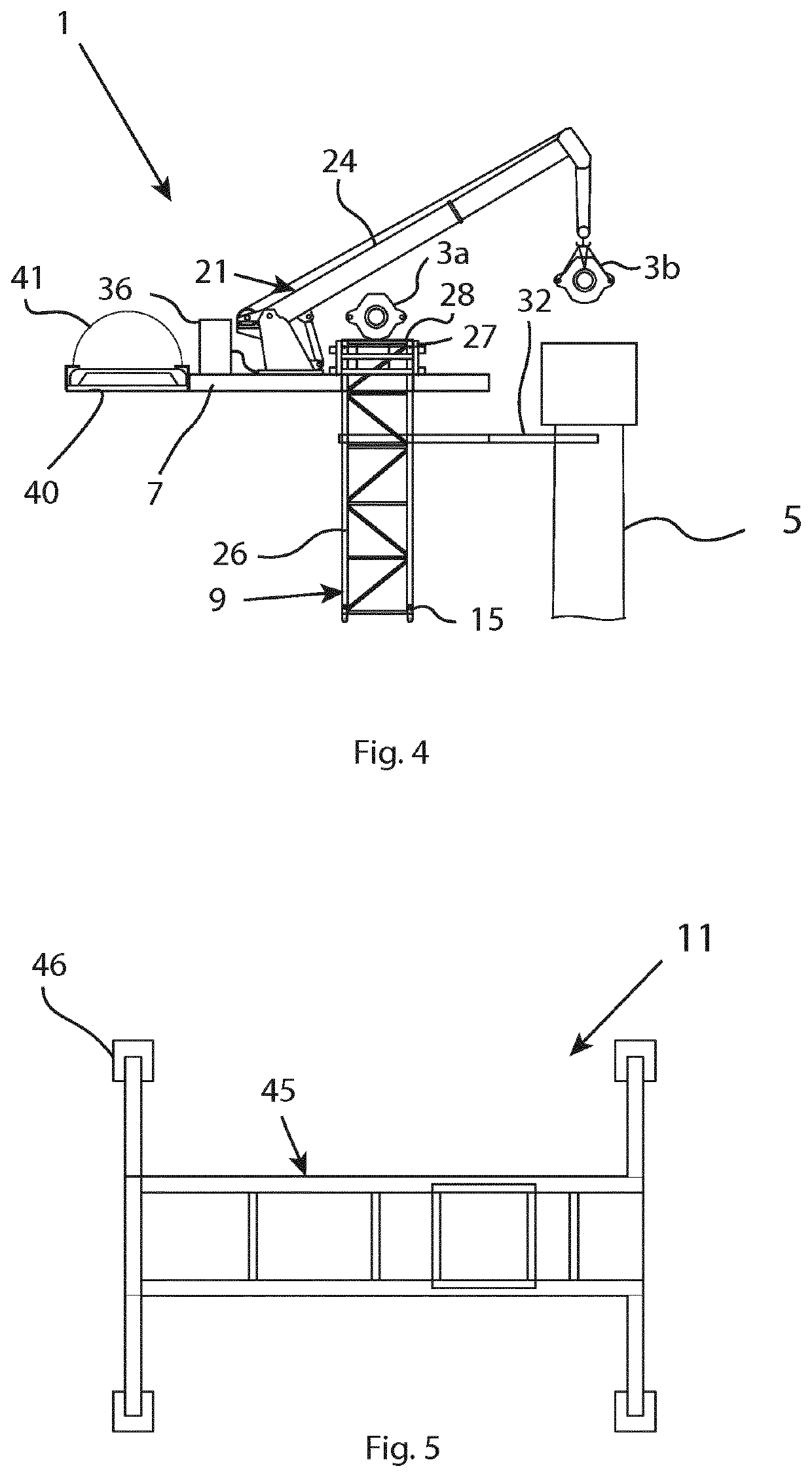
[0084]FIG. 1 shows a lifting assembly 1 for elevating components 3 to a wind turbine 5. The lifting assembly 1 is arranged in close proximity to the wind turbine 5. The lifting assembly 1 comprises a plurality of tower segments 13 which together form an elongated tower 9 with an adjustable height. The lifting assembly 1 further comprises a lifting device 2 including a support frame 11 for supporting the tower, a securing assembly 32 for securing the tower 9 to the wind turbine, a platform 7 arranged linearly moveable relative the support frame 11 and a crane 21 disposed on the platform. The platform 7 is arranged above the support frame 11. The platform is vertically movable in relation to the support frame 11. In this embodiment of the invention, the platform is also linearly moveable relative the tower 9 in a vertical orientation. The platform has a first storage area 19 for supporting components weighing more than 10 tons. The support frame 11 is arranged on the ground and is ada...


PUM


Abstract

A lifting assembly for elevating components to a wind turbine. The lifting assembly comprises a plurality of tower segments adapted to be arranged on top of each other to form an elongated tower, and a lifting device including a support frame for supporting the tower, a securing assembly for securing the tower to the wind turbine, and a crane having a base part and a jib rotatably connected to the base part. The lifting device comprises a platform arranged vertically moveable between a lower and an upper position. The platform has a first storage area for supporting components with a weight of more than 10 tons. The crane is mounted on the platform and is configured to move the components between the platform and the wind turbine when the platform is in the upper position. The platform is provided with an opening adapted to receive the tower segments. The crane and the first storage area are arranged on opposite sides of the opening, and one of the tower segments is a top segment having an upper part provided with a second storage area for supporting components with a weight of more than 10 tons. The invention also relates to a method for using the lifting assembly for replacing an old component of a wind turbine with a new component.

Description

TECHNICAL FIELD[0001]The present invention relates to a lifting assembly for elevating components to the top of a wind turbine. The invention also relates to a method for using the lifting assembly for transportation of components to and from the top of a wind turbine during maintenance of the wind turbine.BACKGROUND OF THE INVENTION[0002]Wind turbines today require regular maintenance of its main components, such as rotor blades, gear boxes and generators. However, these components are often large and heavy, which poses an issue during both the assembly and the maintenance of the wind turbines. For example, the gear boxes may weigh between 20-45 tons, and the generators may weigh between 15-30 tons. Today, the most common solution is to use large, heavy cranes that lifts the components from the ground with long wires. One of the problems with these cranes is that they are highly sensitive to wind, and cannot operate while the wind velocity exceeds certain limits, since the crane be...

Claims


Application Information

Patent Timeline
IPC IPC(8): B66C23/18F03D13/10B66C23/20
CPCB66C23/207F03D13/10B66C23/185F05B2230/61Y02E10/72
Inventor STRANDBERG, MICHAELLUNDBERG, KENNETH
Owner SKYREX AB
Learn More