
Battery pack assembly

Active Publication Date: 2022-10-11
ACELERON LTD
View PDF18 Cites 0 Cited by
  • Summary
  • Abstract
  • Description
  • Claims
  • Application Information

AI Technical Summary

Benefits of technology

The present invention allows for the complete disassembly of a large format battery pack assembly, which has several benefits. Firstly, it enables the replacement of individual cells or components, the reuse of parts at the end of their lifespan, and improved recycling. Secondly, the design of the battery pack assembly helps to meet waste management regulations, saves money and resources, and also allows for the reuse of cells from other applications. Lastly, the design allows for the isolation of failed cells from the other functioning cells in the battery pack assembly, ensuring continued functionality even if one cell fails. Overall, the invention achieves improved efficiency, reliability, and durability of battery pack assemblies.

Problems solved by technology

Such permanent assembly techniques present challenges for repairing or reusing the modules (or the cells or other parts thereof), as the individual components of the assembly cannot easily be accessed or removed.
This also makes it difficult to recycle the modules, as the various materials cannot easily be separated.
Accordingly, such production techniques can lead to energy storage products which are not aligned with EU waste management legislations and prohibits greater revenue opportunities in the repair and repurposing of batteries and battery modules.

Method used


Image

  • Battery pack assembly
  • Battery pack assembly
  • Battery pack assembly

Examples


Embodiment Construction

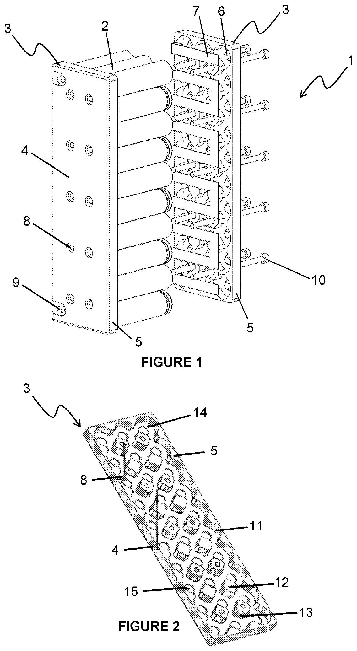
[0044]Referring to FIG. 1, a first embodiment of a battery pack assembly 1 is shown. The battery pack assembly 1 comprises a plurality of lithium-ion cells 2, each cell being held longitudinally between two holding frames 3. The generally rectangular holding frames 3 (which may be made of a plastic material for example) each comprise a generally flat base 4, side walls 5 extending generally perpendicularly from the base 4, elastomeric members 6, conductive plates 7, screw slots 8 and battery terminals 9. The holding frames 3 are reversibly held together by fastening screws 10, with the plurality of cells 2 held in place between the holding frames 3 by the compressive force of the fastening screws 10, which each thread through a screw slot 8 in each of the two holding frames 3.

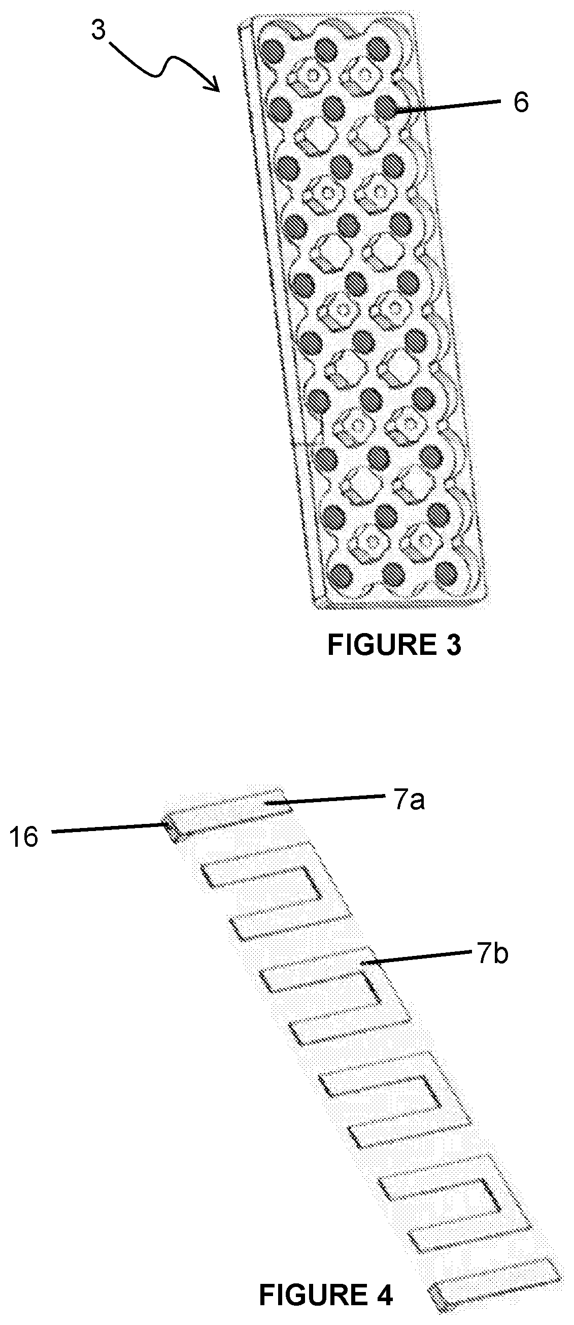
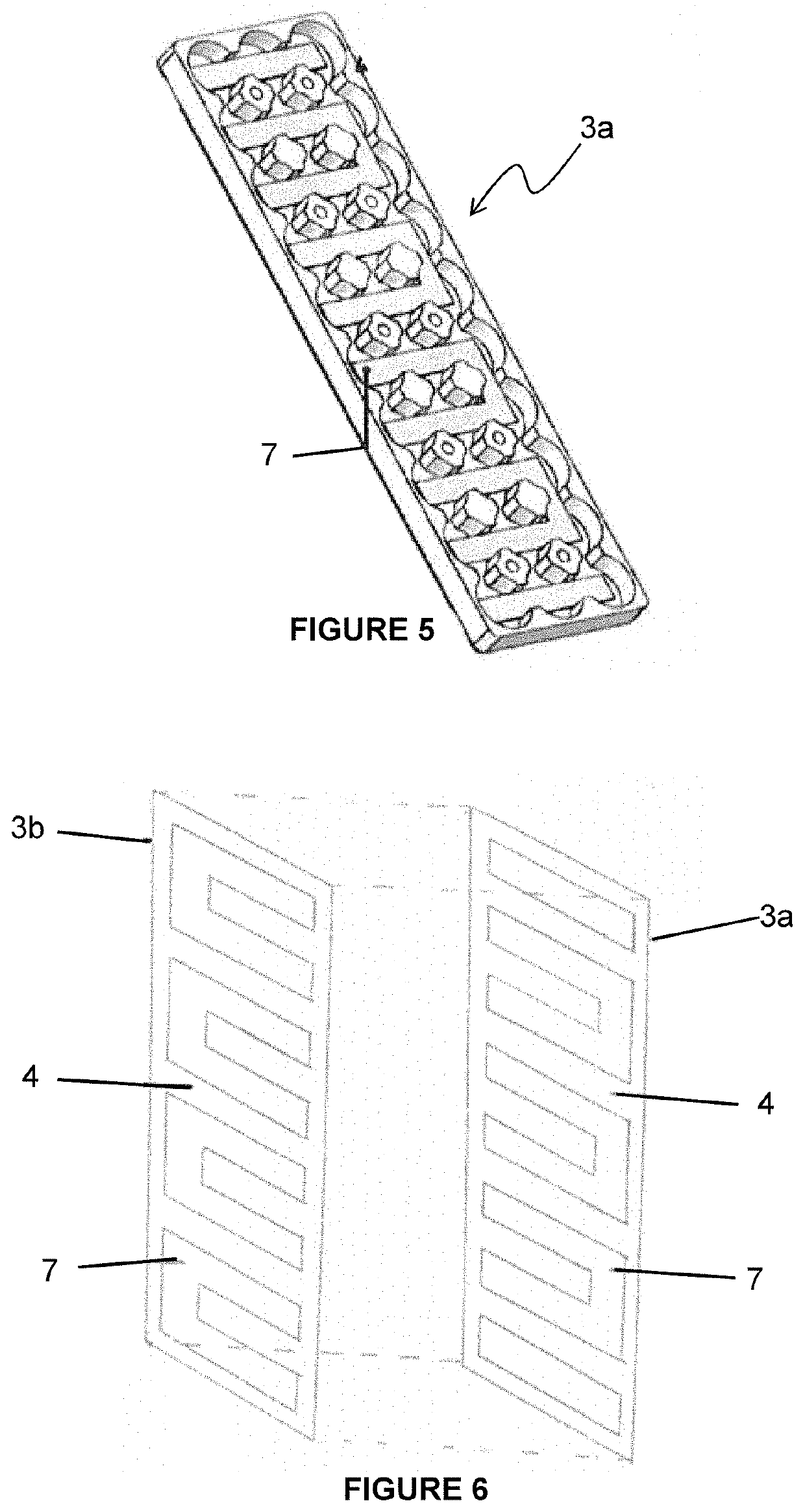
[0045]Referring to FIG. 2, one embodiment of a holding frame 3 is shown. The side walls 5 of the holding frame 3 each comprise a plurality of concave arcuate side wall sections 11. A plurality of base protrusio...


PUM


Abstract

A battery pack assembly (1) comprising two holding frames (3), wherein the two holding frames (3) hold a plurality of cells (2) between them, each cell (2) being held longitudinally between the two holding frames (3), wherein two or more of the plurality of cells (2) are connected by a conductive means (7), and wherein the two holding frames (3) are reversibly held together by a fastening means (10), wherein the fastening means (10) cause terminals of the cells (2) to be urged against the conductive means (7) and removal or loosening of the fastening means (10) enables the cells (2) to be freed from the assembly (1), at least one holding frame (3) comprising one or more elastomeric protrusions (6) and wherein the conductive means (7) are positioned such that parts of them lie between one or more elastomeric protrusions (6) and one or more cell terminals, such that the urging of the frames (3) together by the fastening means (10) causes the conductive means (7) to be urged into contact by the elastomeric protrusions (6) with said one or more terminals.

Description

CROSS REFERENCE TO RELATED APPLICATIONS[0001]This national phase application claims the benefit under 35 U.S.C. § 371 of PCT / GB2017 / 051433, filed May 23, 2017, and whose entire disclosure is incorporated by reference herein.FIELD OF THE INVENTION[0002]The present invention relates to a battery pack assembly. Particularly, but not exclusively, the present invention relates to a lithium-ion battery pack assembly, and particularly to a large format battery pack assembly for example, for use with an electric vehicle such as an electric bike.BACKGROUND OF THE INVENTION[0003]Lithium-ion batteries are known in a variety of cell formats, cylindrical, prismatic and pouch cells are the most common varieties. In a cylindrical cell the electrode is tightly wound about itself and the terminals are typically found at either end of the cylinder, the electrode being contained within a casing, typically made from aluminium. Due to the shape of the cell packing efficiency may be low but the provision...

Claims


Application Information

Patent Timeline
IPC IPC(8): H01M50/20H01M10/48H01M50/502H01M50/213H01M50/271H01M50/503H01M50/51
CPCH01M50/20H01M10/482H01M50/502H01M2220/20H01M50/24H01M50/213H01M50/51H01M50/503H01M50/271Y02E60/10
Inventor CUMMINS, CARLTONCHANDAN, AMRIT
Owner ACELERON LTD
Learn More