Vapor deposition particle emitting device, vapor deposition apparatus, vapor deposition method
a technology of vapor deposition and emitting device, which is applied in the direction of vacuum evaporation coating, chemical vapor deposition coating, coating, etc., can solve the problems of material loss, the proportion of vapor deposition material which has adhered to or accumulated on a place other than the film formation target substrate end up as a material loss, etc., to achieve high display quality panel, suppress blurring of formed film pattern, and disassemble
- Summary
- Abstract
- Description
- Claims
- Application Information
AI Technical Summary
Benefits of technology
Problems solved by technology
Method used
Image
Examples
embodiment 1
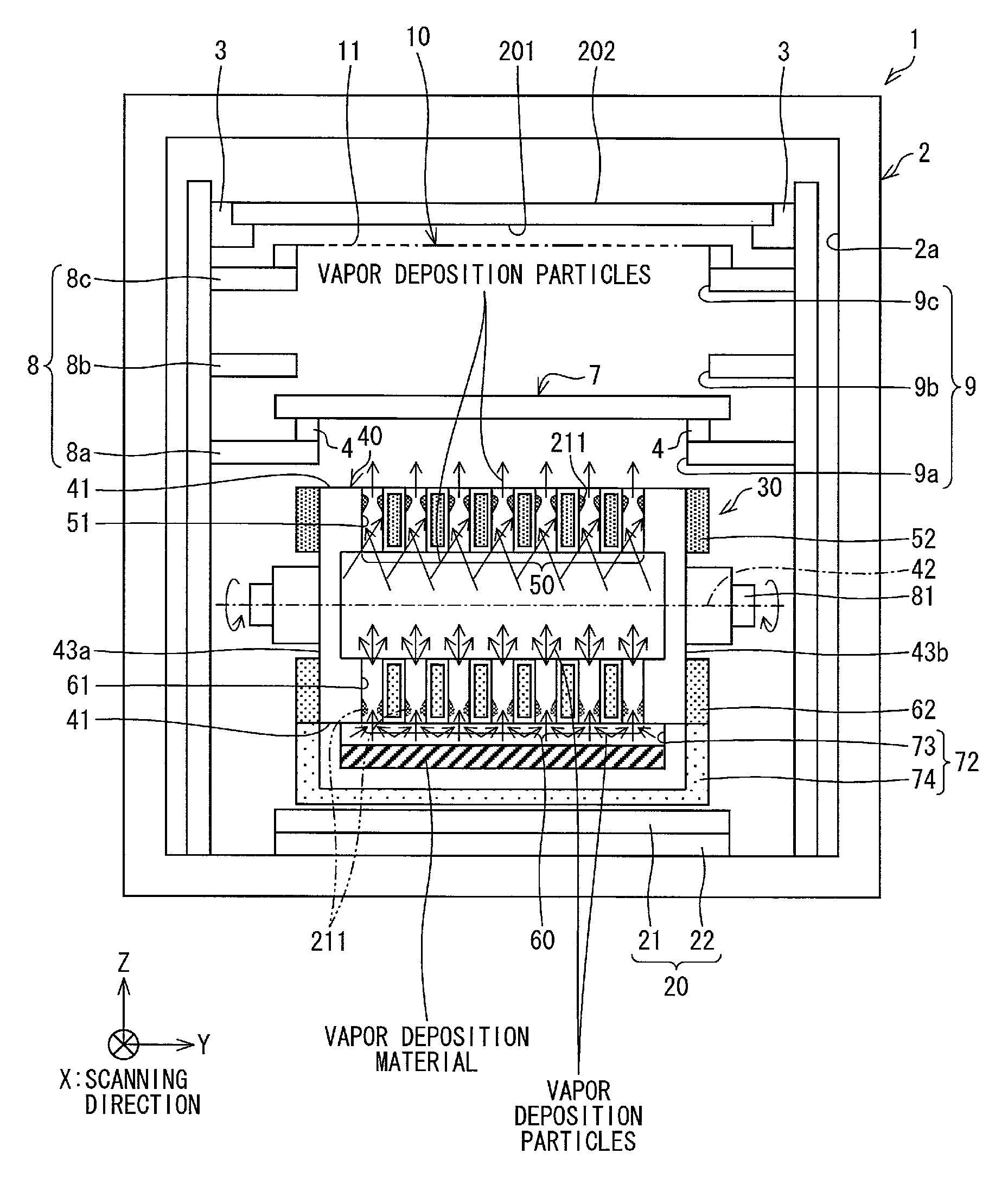
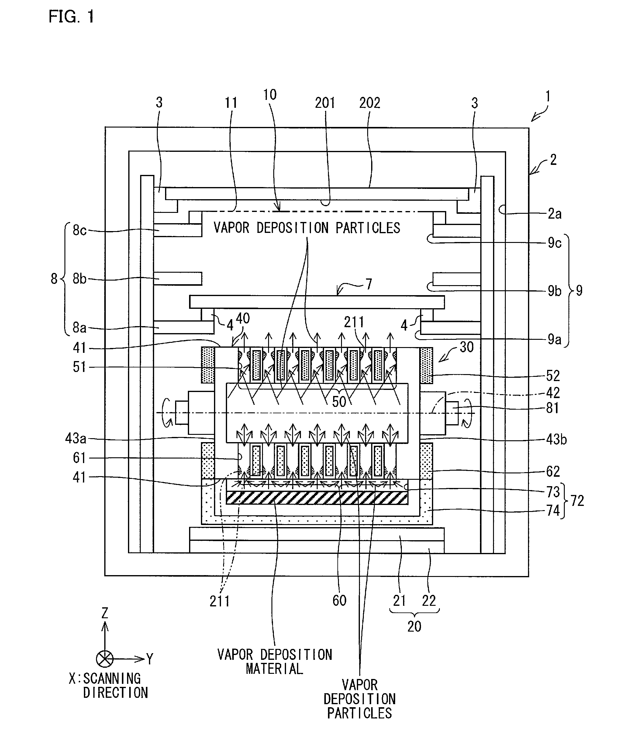
[0077]The following discusses one embodiment of the present invention, with reference to FIGS. 1 through 9.
[0078]
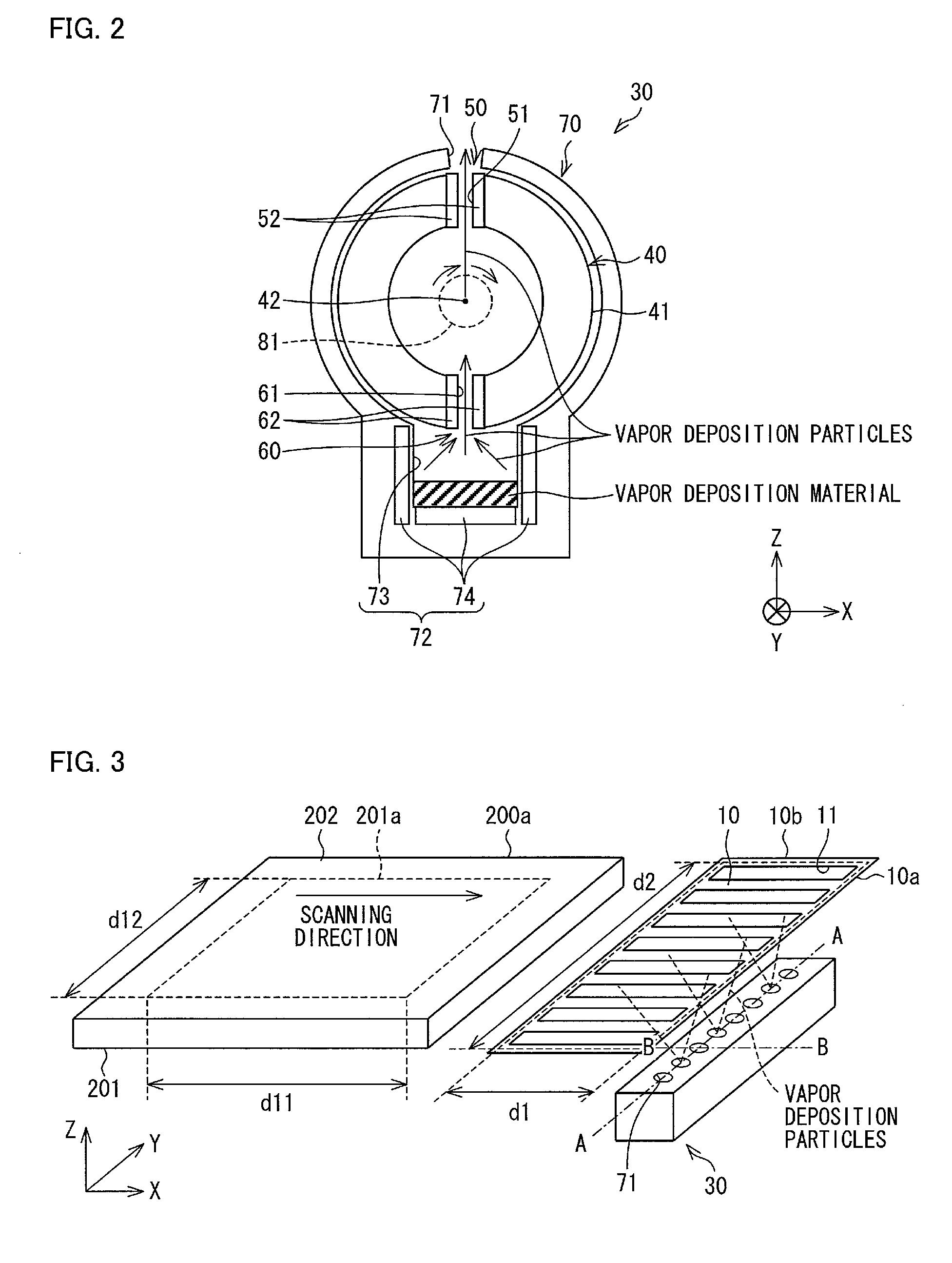
[0079]The following discusses a vapor deposition system employed in a vapor deposition method according to Embodiment 1, with reference to FIG. 3.
[0080]FIG. 3 is an overhead view showing main components in a vacuum chamber in a vapor deposition apparatus according to Embodiment 1. Note that FIG. 3 shows a vapor deposition particle emitting device in a simplified manner.
[0081]As shown in FIG. 3, in the vapor deposition apparatus and the vapor deposition method according to Embodiment 1, vapor deposition, i.e., film formation is carried out in a state where a mask 10 (vapor deposition mask) for vapor deposition, which is called a shadow mask, is arranged to be apart from a film formation target substrate 200.
[0082]In the vapor deposition apparatus and the vapor deposition method according to Embodiment 1, respective positions of the mask 10 and the vapor deposition particle...
embodiment 2
[0368]Embodiment 2 is described below mainly with reference to FIG. 10.
[0369]Embodiment 2 mainly deals with how Embodiment 2 is different from Embodiment 1 above. Constituent elements of Embodiment 2 that are identical in function to their respective equivalents described in Embodiment 1 are each assigned the same reference numeral, and are not described here.
[0370]Embodiment 1 has discussed, as an example, a case where the rotor 40 has one pair of nozzle sections that are provided symmetrically facing each other with the space in the rotor 40 therebetween, one of the nozzle sections being used as a cooled nozzle section and the other as a heated nozzle section.
[0371]Such a pair of nozzle sections may alternatively be provided in a number of two or more.
[0372]FIG. 10 is a cross-sectional view schematically showing a configuration of a vapor deposition particle emitting device 30 according to Embodiment 2.
[0373]FIG. 10 schematically shows a configuration of the vapor deposition parti...
embodiment 3
[0398]Embodiment 3 is described below mainly with reference to FIGS. 11 through 14.
[0399]Embodiment 3 mainly deals with how Embodiment 3 is different from Embodiments 1 and 2 above. Constituent elements of Embodiment 3 that are identical in function to their respective equivalents described in Embodiments 1 and 2 are each assigned the same reference numeral, and are not described here.
[0400]FIGS. 11 and 12 are each a cross-sectional view schematically showing a configuration of a vapor deposition particle emitting device 30 according to Embodiment 3.
[0401]FIG. 11 schematically shows a configuration of the rotor 40 in a cross-section thereof taken along the cylindrical axis. FIG. 12 schematically shows a configuration of the rotor 40 in a cross-section thereof taken along the direction perpendicular to the cylindrical axis.
[0402]The vapor deposition particle emitting device 30 according to Embodiment 3 is similar in operating principle to the vapor deposition particle emitting device...
PUM
| Property | Measurement | Unit |
|---|---|---|
| temperature | aaaaa | aaaaa |
| temperature | aaaaa | aaaaa |
| end-to-end distance | aaaaa | aaaaa |
Abstract
Description
Claims
Application Information
 - R&D
- Intellectual Property
- Life Sciences
- Materials
- Tech Scout
- Unparalleled Data Quality
- Higher Quality Content
- 60% Fewer Hallucinations
Browse by: Latest US Patents, China's latest patents, Technical Efficacy Thesaurus, Application Domain, Technology Topic, Popular Technical Reports.
© 2025 PatSnap. All rights reserved.Legal|Privacy policy|Modern Slavery Act Transparency Statement|Sitemap|About US| Contact US: help@patsnap.com


