
Dynamometer device and method for assembling same

a dynamometer and disassembly technology, applied in the direction of engine testing, structural/machine measurement, instruments, etc., can solve the problems of increasing the number of steps and the time accompanied by the disassembly of the dynamometer device, and achieve the effect of disassembling the first bed and being easy to remov

Active Publication Date: 2020-03-17
MEIDENSHA ELECTRIC MFG CO LTD
View PDF10 Cites 0 Cited by
  • Summary
  • Abstract
  • Description
  • Claims
  • Application Information

AI Technical Summary

Benefits of technology

[0008]Consequently, it is possible to disassemble the first bed substantially integrated with the dynamometer by removing it from the second bed of the tank and to reassemble it.
[0009]According to the present invention, at the time of the disassembling of the dynamometer device, the dynamometer can be easily removed from the tank because it is only necessary to take down the first bed on a dynamometer side from the second bed on a tank side.

Problems solved by technology

However, in the dynamometer device of the patent document 1, for example, at the time of disassembling for maintenance, it is necessary to remove a plurality of the components of the dynamometer from the bed of the tank individually, and there is possibility that the number of the steps and the time accompanied with the disassembling of the dynamometer device increases.

Method used


Image

  • Dynamometer device and method for assembling same
  • Dynamometer device and method for assembling same
  • Dynamometer device and method for assembling same

Examples


Embodiment Construction

[0018]In the following, one embodiment of the present invention will be explained with reference to the drawings.

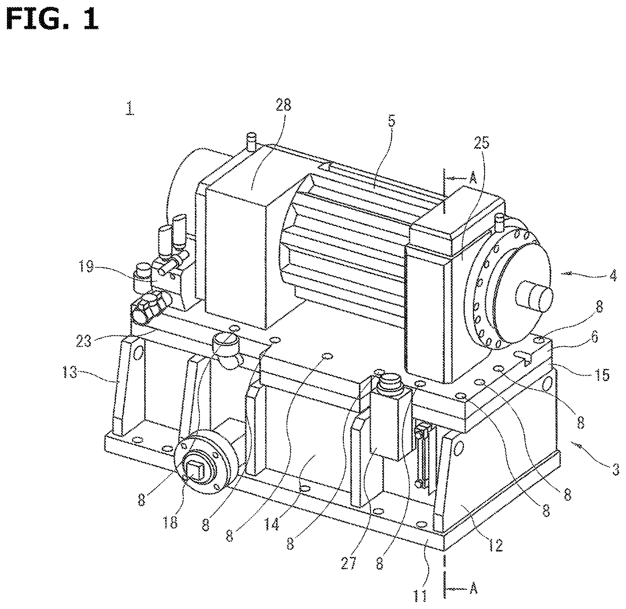
[0019]In FIG. 1, an oil-cooled dynamometer device 1 in one embodiment of the present invention is shown. The dynamometer device 1 is used to perform performance evaluation and a durability test by using, for example, an engine, a transmission or the like of a vehicle as a test body.

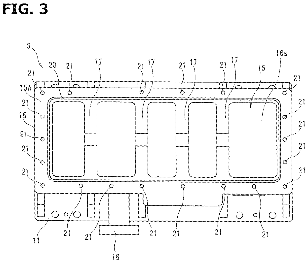
[0020]The dynamometer device 1 is equipped with a bed tank 3 for storing a cooling oil 2 as a cooling medium and a dynamo body 4 provided on this bed tank 3.

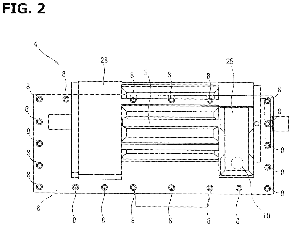
[0021]The dynamo body 4 is equipped with a long narrow dynamometer 5 formed in a substantially cylindrical shape and a plate-shaped dynamometer-side bed 6 on which this dynamometer 5 is placed. The dynamometer 5 accommodates a rotor, a stator, coils, permanent magnets and the like which are not shown in the drawings. In addition, an auxiliary machine terminal box 28 for accommodating terminals for an auxiliary machine which is not shown in ...


PUM

PropertyMeasurementUnit
durability testaaaaaaaaaa
durabilityaaaaaaaaaa
cylindrical shapeaaaaaaaaaa

Abstract

A dynamometer (5) in a dynamometer device (1) is assembled on the top of a dynamometer-side bed (6), and the dynamometer-side bed (6) is removably attached to a tank-side bed (15) located on the top part of a bed tank (3). Consequently, at the time of the disassembling of the dynamometer device (1) for maintenance or the like, it is possible to easily separate a dynamo body (4) and the bed tank (3) from one another by simply taking down the dynamometer-side bed (6) from the tank-side bed (15).

Description

TECHNICAL FIELD[0001]The present invention relates to a dynamometer device in which a dynamometer is placed on a tank.BACKGROUND TECHNOLOGY[0002]In a patent document 1, a dynamometer device for performing performance evaluation and a durability test by using, for example, an engine as a test body has been disclosed. In this dynamometer device, a dynamometer is assembled on the top of a tank for storing a cooling medium. A plurality of components composing the dynamometer are individually attached to a bed on the top of the tank.[0003]However, in the dynamometer device of the patent document 1, for example, at the time of disassembling for maintenance, it is necessary to remove a plurality of the components of the dynamometer from the bed of the tank individually, and there is possibility that the number of the steps and the time accompanied with the disassembling of the dynamometer device increases.[0004]Therefore, an object of the present invention is to provide a dynamometer devic...

Claims


Application Information

Patent Timeline
Patent Type & Authority Patents(United States)
IPC IPC(8): G01L3/00G01L3/16G01M15/02G01M17/007
CPCG01L3/16G01M17/007G01M15/02G01M15/04
Inventor SHIMIZU, TAKAHIROWATANABE, SHIGEO
Owner MEIDENSHA ELECTRIC MFG CO LTD
Learn More