Vacuum cleaner

A technology for vacuum cleaners and dust suction, which is applied in the direction of suction filters, devices for cleaning filters, etc., and can solve problems such as adhesion

Inactive Publication Date: 2009-06-24
TOSHIBA LIFESTYLE PROD & SERVICES CORP
View PDF0 Cites 9 Cited by
  • Summary
  • Abstract
  • Description
  • Claims
  • Application Information

AI Technical Summary

Problems solved by technology

[0005] However, in this vacuum cleaner, there is a problem that when the electric blower is driven, the dust falling off from the pleated filter adheres to the pleated filter again.

Method used


Image

  • Vacuum cleaner
  • Vacuum cleaner
  • Vacuum cleaner

Examples


no. 1 example

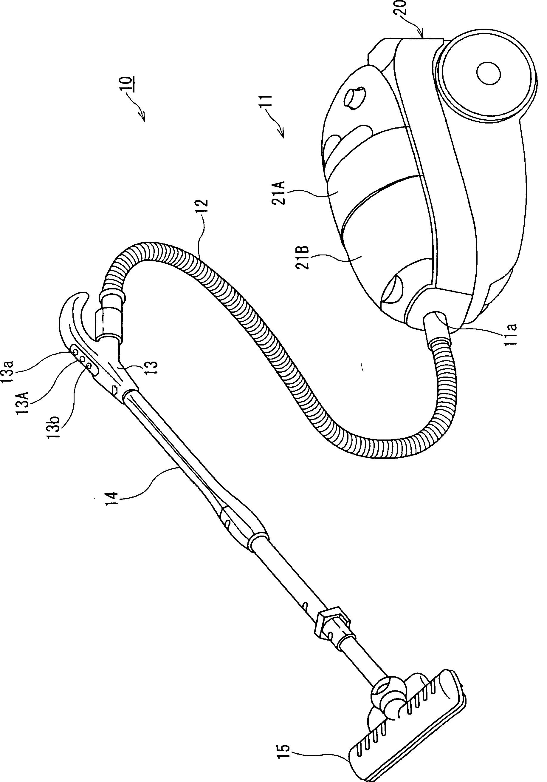
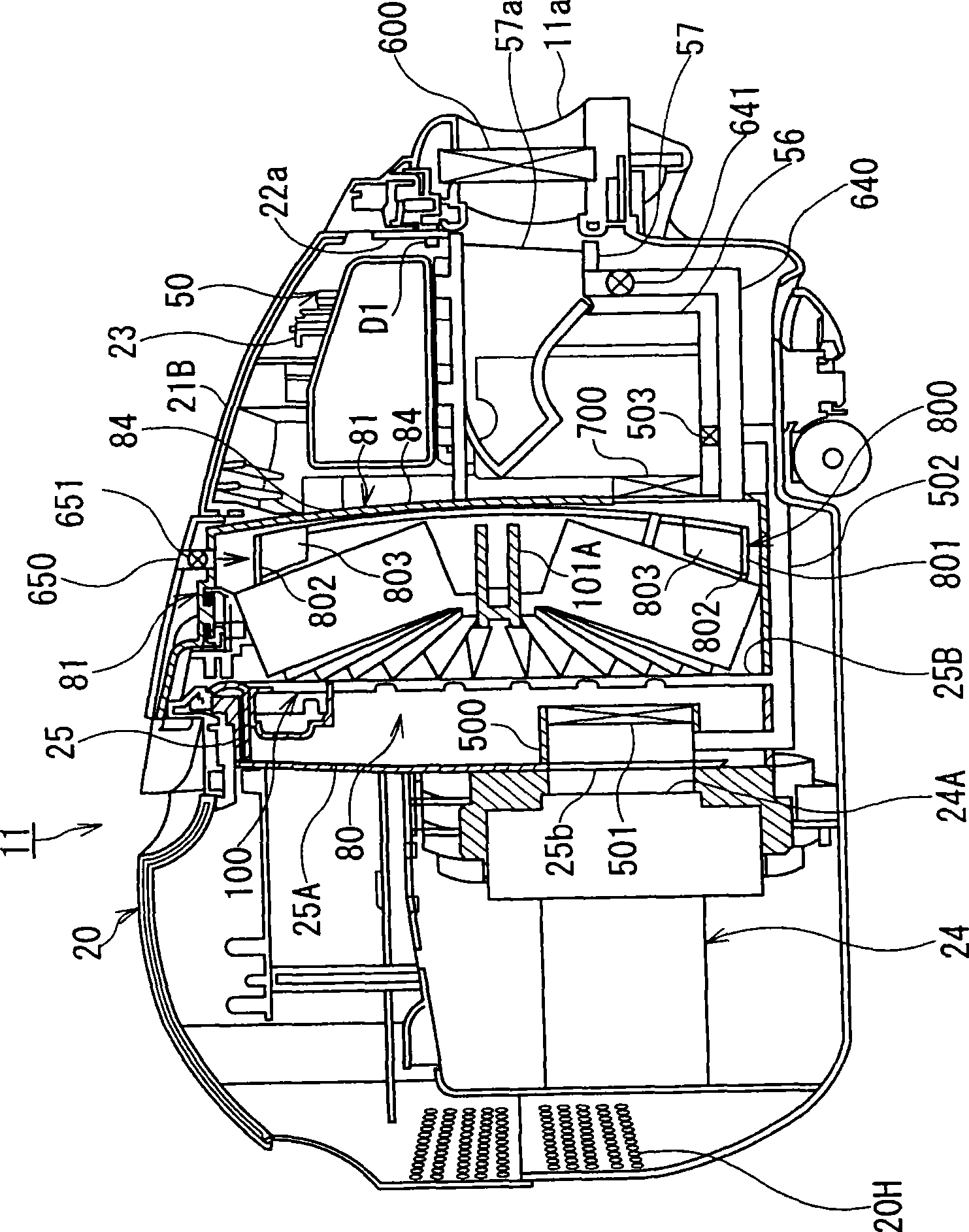
[0030] figure 1 A vacuum cleaner according to a first embodiment of the invention is shown. The vacuum cleaner 10 in the first embodiment comprises: a cleaner main body 11; a dust collecting hose 12, one end of which is detachably connected to the connection hole 11a of the cleaner main body 11, and the other end is provided with a hand-operated tube 13; an extension tube 14, detachable and the suction hole main body 15 is detachably connected to the front end of the extension pipe 14. The hand-operated pipe 13 has an operating part 13A, which includes a drive / stop switch 13a for switching between driving and stopping the electric blower 24, and a strong / weak switch 13b for controlling the electric blower 24 power, described below. The cleaner main body 11 has a main body housing 20 incorporating a dust collection unit 50 and an electric blower 24 (see figure 2 ). These dust collection units 50 and electric blower 24 are described below.

[0031] The suction hole main bo...

no. 2 example

[0077] Figure 9 and 10 A vacuum cleaner according to a second embodiment of the invention is shown. In the vacuum cleaner of the second embodiment, the air passage pipe 500 and the inside of the accommodating case 81 communicate through a detour air passage 900 which constitutes a detour passage and which has a third dust separation unit. The third dust separation unit includes, for example, a filter 901 and a solenoid valve 902 .

[0078] In the vacuum cleaner of the second embodiment, when cleaning, the gates 501 and 700 are opened, the solenoid valve 902 is closed, and the air flows as Figure 10 As shown by the chain line with arrows in , and the dust is collected in the dust collection cavity part 73, same as the first embodiment.

[0079] When the switch 13a (see figure 1 ), the gates 501 and 700 are closed, and the solenoid valve 902 is opened. The electric blower 24 is driven with predetermined power for a predetermined period of time.

[0080] When the shutters...


PUM


Abstract

A vacuum cleaner has an electric blower (24) for causing dust and dirt to be sucked from a suction-connection port (57a), a first dust and dirt separator for separating from each other the dust / dirt and air sucked into the suction-connection port (57a), and a pleated filter (104) for separating from each other the dust / dirt and air passing through the first dust and dirt separator. The vacuum cleaner further has an outside air introducing air passage tube (650) for introducing the outside air to the upstream side of the pleated filter (104), a rotating fan (800) for removing, by the introduced outside air, the dust and dirt adhered to the pleated filter (104), and a return air passage (640) for returning, by the introduced outside air, the dust and dirt removed by the rotating fan (800) to the upstream side of the first dust and dirt separator.

Description

technical field [0001] The present invention relates to a vacuum cleaner, and more particularly, to a vacuum cleaner capable of preventing dust falling from a collecting unit, such as a filter, for collecting the dust from re-adhering to the collecting unit. Background technique [0002] Heretofore, there has been known a vacuum cleaner comprising: a cleaner main body provided with a dust collection housing formed therein; a dust collection container detachably attached to the dust collection housing; an electric blower provided in the dust collection housing; on the downstream side of the pleated filter; an auxiliary filter, such as a pleated filter, detachably mounted to the rear opening of the dust collection container for collecting dust; and a dust removal unit for detaching the dust adhering to the pleated filter (See Japanese Unexamined Patent Application Publication No. 2004-358135). [0003] This dust removing unit includes a ring provided at a position opposite to...

Claims


Application Information

Patent Timeline
Patent Type & Authority Applications(China)
IPC IPC(8): A47L9/16A47L9/20
CPCA47L9/20A47L9/10A47L9/16
Inventor 森下笃至竹本律雄松下裕一土屋善弘
Owner TOSHIBA LIFESTYLE PROD & SERVICES CORP
Why Eureka
Try Eureka