Bottle stopper

A technology of bottle stopper and stopper body, applied in the field of bottle stopper, can solve the problems of flow out of content, difficult to hold and apply force, and bottle body toppling, etc., and achieve the effects of good tightness, convenient storage and arrangement, and convenient holding.

Inactive Publication Date: 2009-07-01
王吴静月
View PDF0 Cites 9 Cited by
  • Summary
  • Abstract
  • Description
  • Claims
  • Application Information

AI Technical Summary

Problems solved by technology

[0002] After the general bottle body is unsealed, most of its contents (such as wine, champagne... etc.) cannot be drunk at one time, so a kind of bottle stopper 1 is used to cover the bottle mouth 19. Please refer to figure 1 , figure 2 As shown, mainly an elastic body 11, a positioning block 12 and another elastic body 13 are sequentially sleeved on the shaft 10, and an enlarged part 100 is provided at the bottom end of the shaft 10 for blocking the above-mentioned components, and The upper end of the shaft rod 10 is stretched through the cover 14 and a gasket 15, and then the puller body 16 is pivotally connected to the upper end of the shaft rod 10 by means of a pivot 160, so that the puller body 16 is pressed downward to make the The pressing part 161 at the lower end of the wrench body 16 is pressed against the gasket 15 above the cover 14 to make the shaft 10 rise, and the enlarged part 100 and the positioning block 12 at the bottom of the shaft 10 squeeze the elastic body 11 to make the elastic Body 11 deforms and expands outwards, and bottleneck 19 is plugged, and then, when existing bottle stopper 1 cover is located on bottleneck 19 and desires to plug, must forcefully pull and press pull body 16, pull and press pull body 16 When pressing down on one side, it is easy to cause the overall center of gravity to be unstable due to applying force to the side, and the bottle body is easy to topple over to one side, so that the contents flow out, and the sealing cap 14 is only closed on the upper edge of the bottle mouth 19, and its tightness The fit is not good, and it is not easy to hold and apply force, and the shaft 10, the elastic body 11, 13 and the positioning block 12 are exposed outside the cover 14, which is easy to be contaminated with dust and dirt when not in use, making it unclean and unhygienic in use , and the above-mentioned kind of bottle stopper 1 cannot be placed flat, and it is inconvenient to store

Method used


Image

  • Bottle stopper
  • Bottle stopper
  • Bottle stopper

Examples


Embodiment Construction

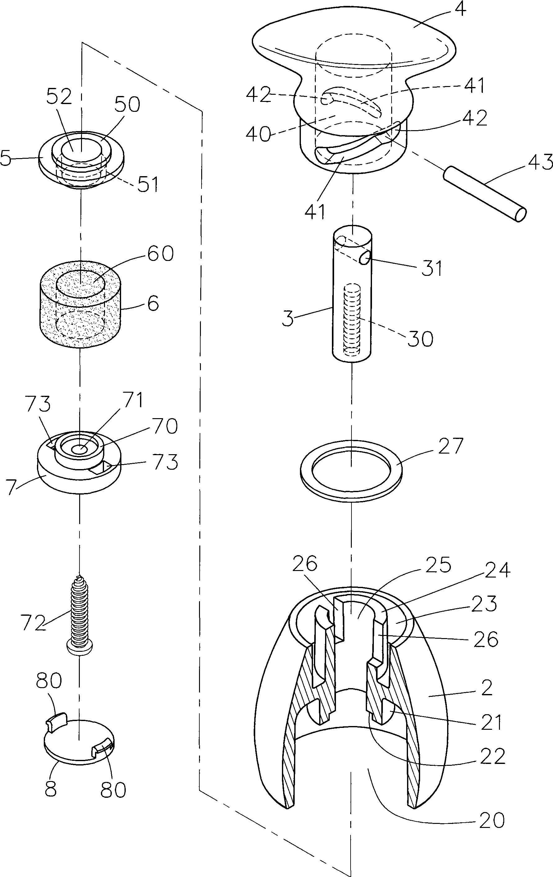
[0015] Relevant present invention is for reaching above-mentioned purpose of use and effect, the technical means that adopts, presents preferred feasible embodiment hereby, and cooperates as shown in the drawing, is described in detail as follows:

[0016] For an example of the invention, see Figure 3 ~ Figure 5 As shown, it is mainly provided with a cover body 2, the bottom of the cover body 2 is provided with an alcove 20, and a protruding post 21 is arranged in the alcove 20, and a groove 22 is provided on the bottom surface of the protruding post 21. The top surface of the body 2 is provided with an annular groove 23, and a convex seat 24 is provided in the annular groove 23, and a shaft hole 25 is provided in the convex post 21 to penetrate to the top surface of the convex seat 24, and the convex seat 24 A guide groove 26 is oppositely provided on the wall surface, and a gasket 27 is arranged in the ring groove 23; a shaft rod 3 is penetrated in the shaft hole 25 of the ...


PUM


Abstract

The invention relates to a bottle stopper, which mainly comprises a cover body, a shaft rod, a rotor body, a connecting seat, a stopper body and a fixed seat, wherein the shaft rod is extended into the cover body; the rotor body and the shaft rod are inserted and assembled on the cover body through a latch pin; the connecting seat, the stopper body and the fixed seat are connected to the lower end of the shaft rod through fixedly connecting elements and positioned inside a concave chamber at the bottom of the cover body; and the latch pin leans against the inside of a relative oblique chute on the rotor body and is limited by a guide groove of a convex seat in the cover body. When the rotor body rotates, the latch pin slides in the oblique chute on the rotor body, can not rotate along with the rotor body because the latch pin is limited by the guide groove, move up and drive the shaft rod to rise, and the fixed seat at the lower end of the shaft rod rises along with the shaft rod and extrudes the soft stopper body which is extruded and expanded outwards and stops up a bottle mouth. The bottle stopper is quite convenient to use, can seal and stop up the bottle mouth, is sanitary because a rod body and the stopper body are hidden and not exposed, and can be flatly laid and stored.

Description

technical field [0001] The invention relates to a bottle stopper, in particular to a bottle stopper which can close the bottle mouth tightly, is extremely hygienic, and can be placed flat for storage. Background technique [0002] After the general bottle body is unsealed, most of its contents (such as wine, champagne... etc.) cannot be drunk at one time, so a kind of bottle stopper 1 is used to cover the bottle mouth 19. Please refer to figure 1 , figure 2 As shown, mainly an elastic body 11, a positioning block 12 and another elastic body 13 are sequentially sleeved on the shaft 10, and an enlarged part 100 is provided at the bottom end of the shaft 10 for blocking the above-mentioned components, and The upper end of the shaft rod 10 is stretched through the cover 14 and a gasket 15, and then the puller body 16 is pivotally connected to the upper end of the shaft rod 10 by means of a pivot 160, so that the puller body 16 is pressed downward to make the The pressing part...

Claims


Application Information

Patent Timeline
Patent Type & Authority Applications(China)
IPC IPC(8): B65D41/28B65D39/12B65D39/16
Inventor 王吴静月
Owner 王吴静月
Why Eureka
Try Eureka