Driving device for leaf of door or window

A driving device and leaf-leaf technology, applied in door/window fittings, wing leaf parts, switches with brakes, etc., can solve the problems of door closers, such as possible solutions, durability and operating comfort.

Active Publication Date: 2009-07-01
盖泽工业(天津)有限公司
View PDF2 Cites 11 Cited by
  • Summary
  • Abstract
  • Description
  • Claims
  • Application Information

AI Technical Summary

Problems solved by technology

However, this constant relatively high pressure level in the hydraulic system of the drive has a negat

Method used


Image

  • Driving device for leaf of door or window
  • Driving device for leaf of door or window
  • Driving device for leaf of door or window

Examples


Embodiment Construction

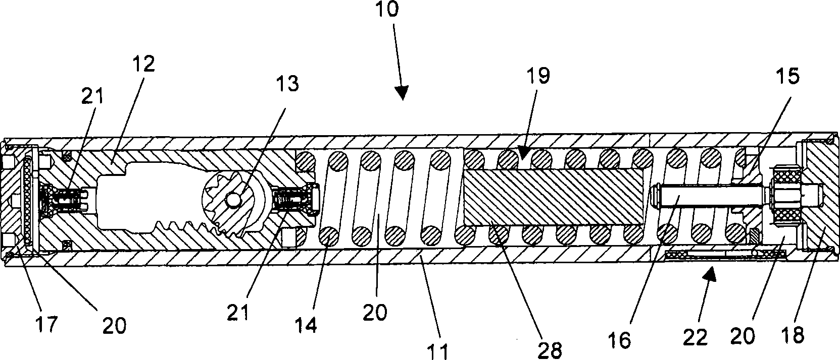
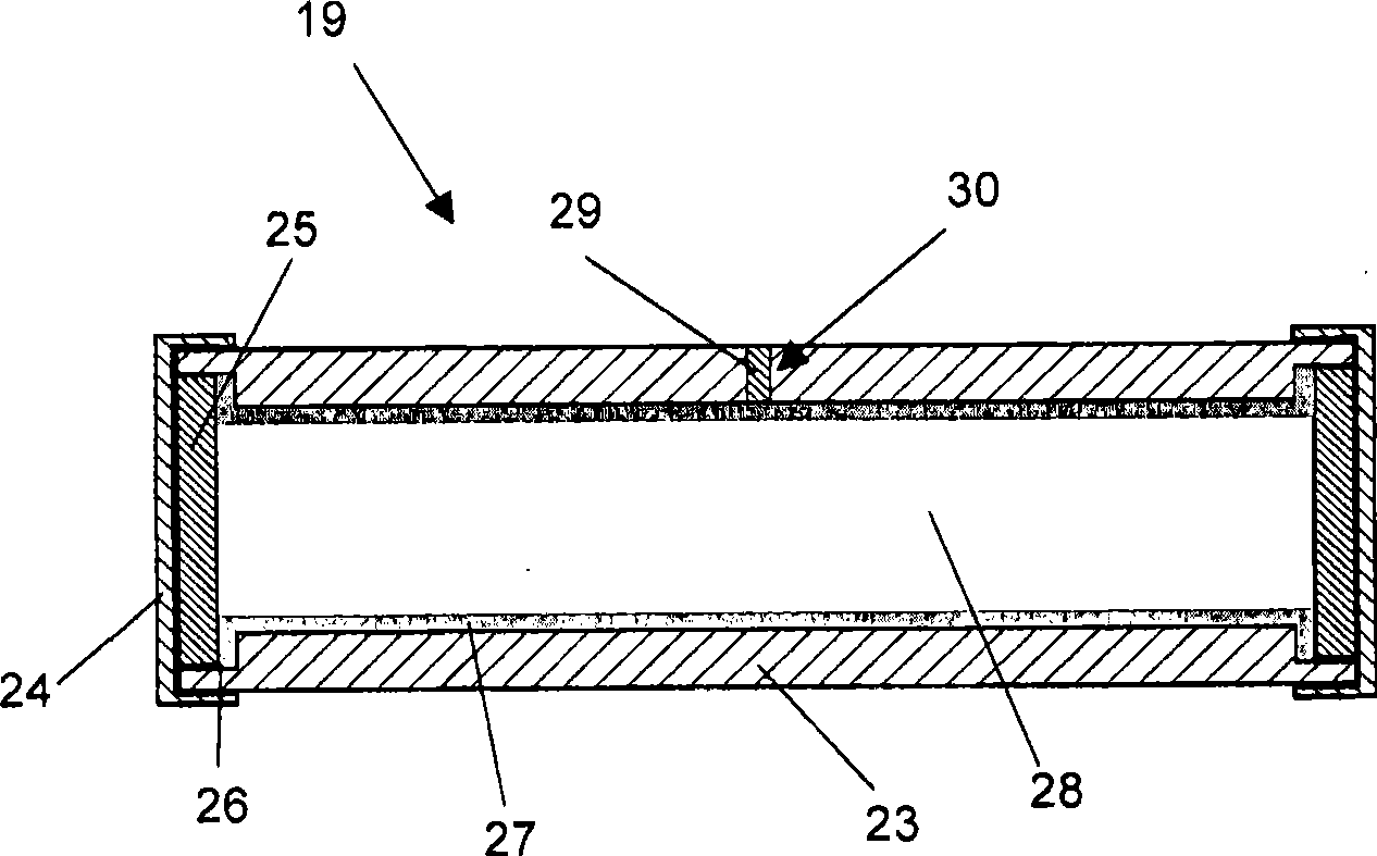
[0022] exist figure 1 A horizontal section through a drive device 10 designed as a door closer can be seen in FIG. The drive device 10 comprises: a housing 11 configured as a cylindrical tube as the main component; a working piston 12 guided linearly displaceably in a bore of the housing 11 and engaging a transmission gear 13 in its toothed rack a helical compression spring 14, which is supported axially between a ring end face of the working piston 12 and an opposite ring end face of a spring disk 15, wherein the spring disk 15 can be moved axially relative to the working piston 12 is guided along an adjusting screw 16; a housing cover 17 for closing on the left end of the housing 11 and a housing cover 18 for closing on its right end and a cylindrical compensating container 19 , which is arranged in the hollow cross-section of the helical compression spring 14 . The spring force is adjustable, since the spring disk 15 is adjustable along the adjusting screw 16 from the out...


PUM


Abstract

A driving device used for a fan blade includes a shell, and a preset fluid volume inside a closed system, wherein the fluid volume changes because of heat expansion and that can be compensated by a gas volume acted by the fluid, and the gas volume that has compensating effect is surrounded by a flexible outer housing; the fluid pressure of the driving device is acted on the peripheral surface of the outer housing. The driving device also includes a work piston and a screw pressure spring. Through the open and rotation of the fan blade, a forced rotation of a transmission gear relevant to a fan blade opening angle is generated, thus the spring is compressed when the work piston is moved, and one compensation container is arranged in a hollow cross section of a spring winding of the spring. The outer housing is housed by the compensation container and an outside surface is communicated and connected with the flow through a connection channel which is configured to be a throttle position and to form a high pass filter relative to the flow.

Description

technical field [0001] The invention relates to a drive for a door or window leaf according to the preamble of claim 1 . Background technique [0002] Such a drive is already known from DE 10 2004 031 936 A1 as prior art. The drive for a door closer comprises a cylindrical housing, in which a working piston, which is kinematically connected to the door leaf via a gear, is guided linearly displaceable. The hollow cylinder, which is filled with hydraulic fluid as damping medium, is divided into two hollow chambers by the working piston, which is acted on axially by a shutter spring. Depending on the position of the working piston, these hollow chambers communicate with each other via overflow channels, so that the compressed hydraulic fluid can overflow from one hollow chamber to the other under the damping of the movement of the working piston, depending on its direction of movement. When the door leaf is swung open, the working piston is thus moved due to its kinematic con...

Claims


Application Information

Patent Timeline
IPC IPC(8): E05F3/10
CPCE05F3/102E05Y2201/492E05Y2400/818E05F3/12E05Y2201/448E05Y2800/00E05F3/227E05Y2900/132
Inventor W·默尔根
Owner 盖泽工业(天津)有限公司
Why Eureka
Try Eureka