Service providing system, gateway, and server

A service gateway and server technology, applied in the field of systems that provide network services, can solve the problems of reduced network utilization efficiency, inability to perform processing, and large servers, and achieve the effects of reducing equipment investment and speeding up conversion time.

Inactive Publication Date: 2009-07-01
HITACHI LTD
View PDF1 Cites 9 Cited by
  • Summary
  • Abstract
  • Description
  • Claims
  • Application Information

AI Technical Summary

Problems solved by technology

[0005] However, it is difficult to solve the following problems caused by the increase of upload traffic in these technologies
First, since the uploading destination server is installed in a small number of bases, if uploading is performed simultaneously and in parallel from client groups scattered over a wide area, it will place a heavy load on the server
Second, since the traffic from the client group to the server is gradually concentrated, congestion occurs at a certain point when the line capacity is exceeded, and the utilization efficiency of the network is significantly reduced
The reason for this is that a general Web service is a system in which subsequent processing cannot be performed unless the uploaded content is transmitted to the server.

Method used


Image

  • Service providing system, gateway, and server
  • Service providing system, gateway, and server
  • Service providing system, gateway, and server

Examples


Embodiment 1

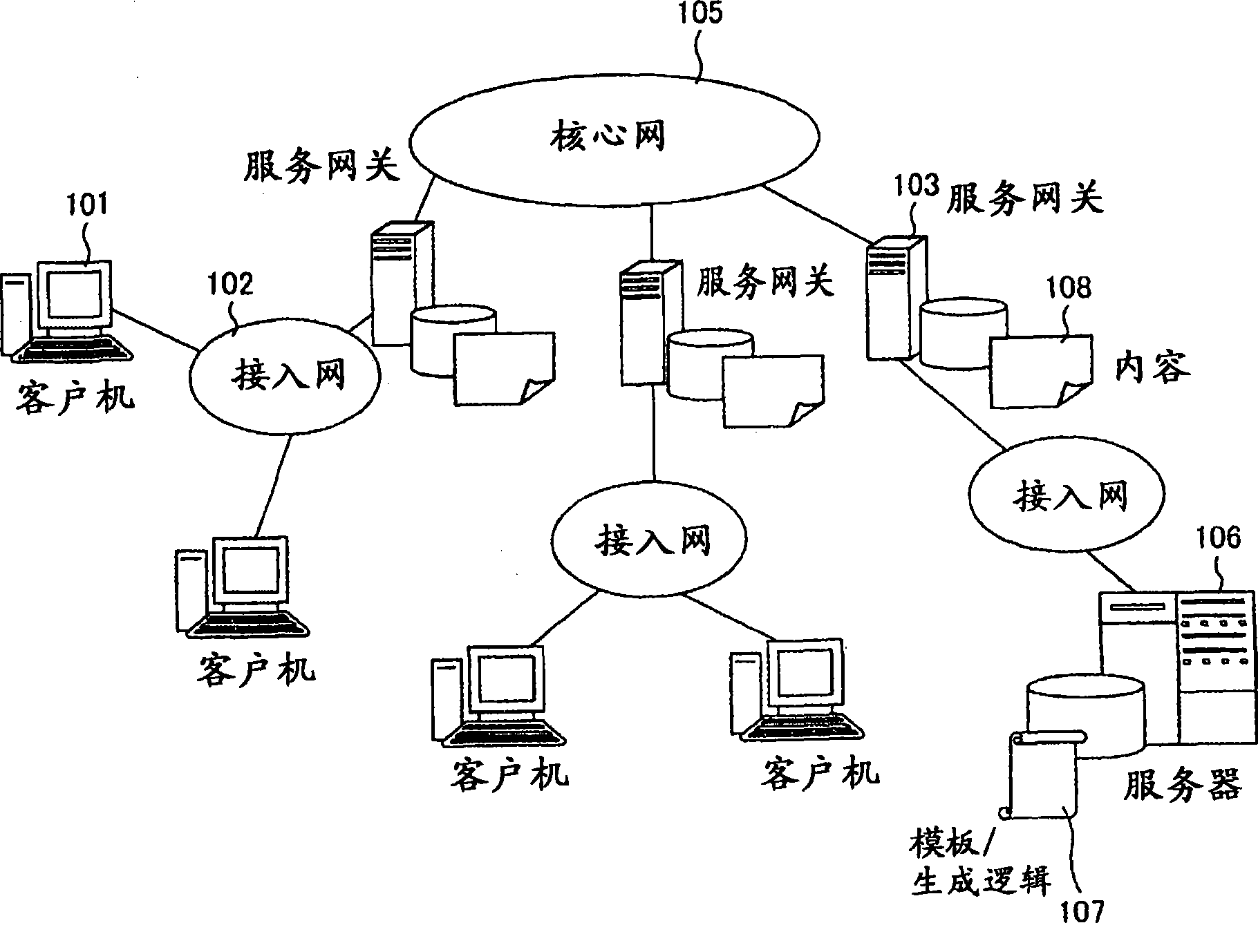
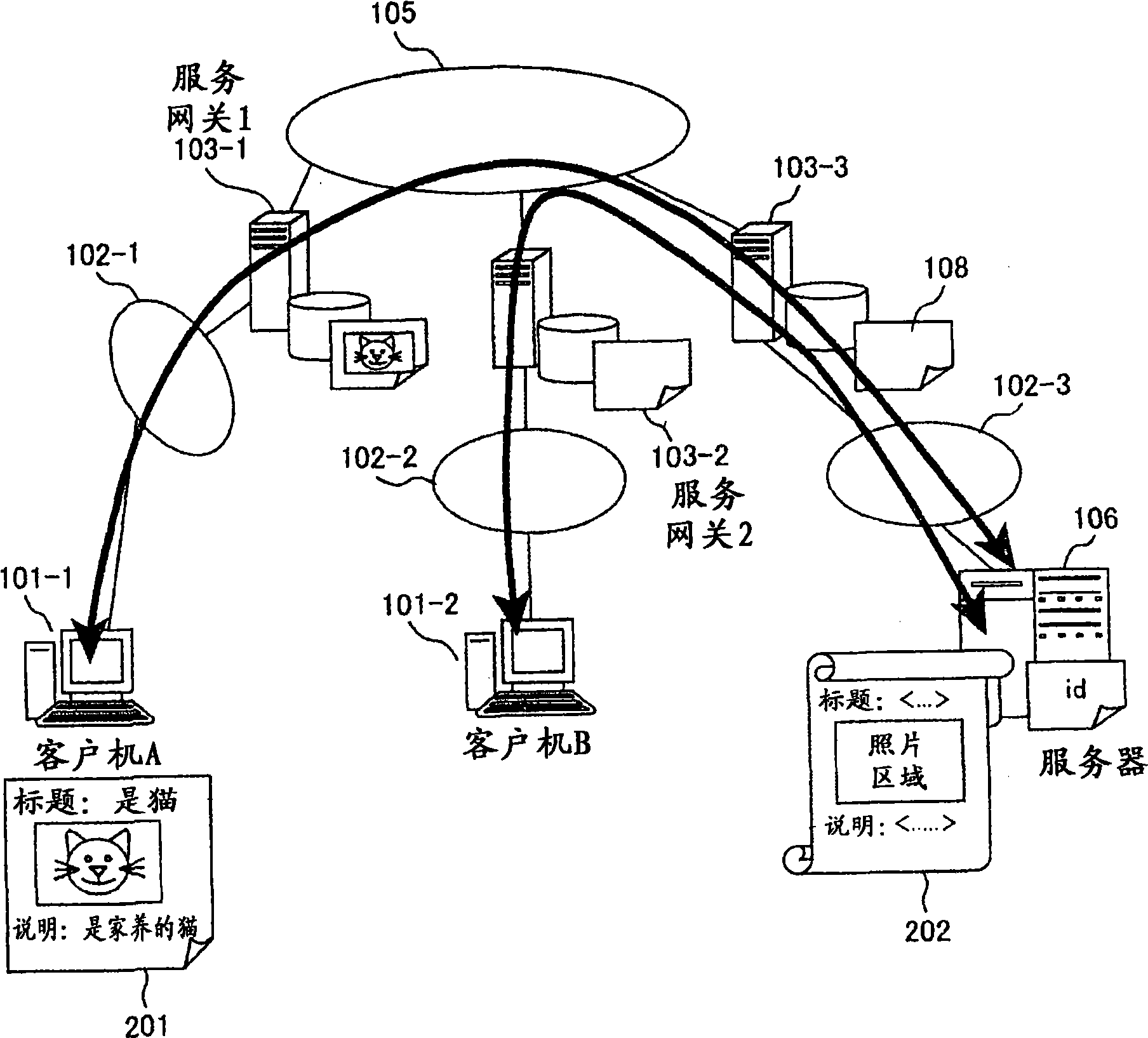
[0068] In the distributed service providing system in the first embodiment, a Web-based image registration system is described. figure 2 It is a diagram showing an example of the structure of the distributed service providing system of the first embodiment.

[0069] The distributed service providing system of Embodiment 1 includes clients 101-1-2, access networks 102-1-3, service gateways 103-1-3, and core network 105.

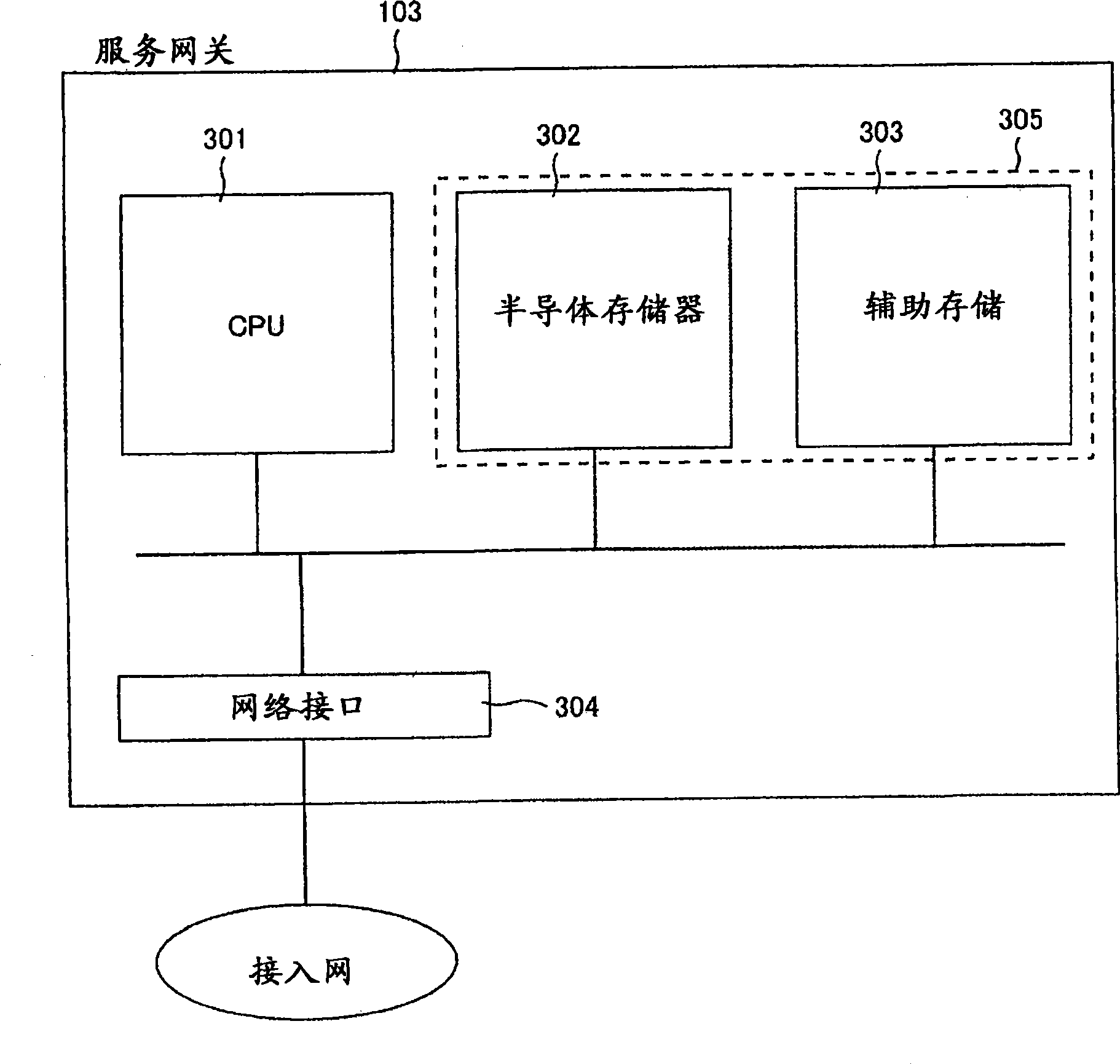
[0070] The service gateway 103 is as image 3 Shown is a computer including a central processing unit (Central Processing Unit, CPU) 301 , a semiconductor memory 302 , an auxiliary storage 303 , and a network interface 304 . Since the semiconductor memory 302 and the auxiliary storage 303 are similarly treated as a storage unit (memory) in this embodiment, they will be collectively and simply referred to as the memory 305 hereinafter. The network interface 304 for transmitting and receiving data is connected to the access network 102 and the core network 10...

Embodiment 2

[0108] As a second embodiment, an embodiment in which advertisement insertion for content is realized is shown. The difference with embodiment 1 is: as Figure 17 As shown, an advertisement server 1701 for managing advertisement manuscripts and a user attribute server 1702 for managing user attributes are added to the structure, and an area for filling in advertisements is defined in the template answered from the server 106; attribute and fetches an ad based on that attribute.

[0109] exist Figure 17 In , although the advertisement server 1701 and the user attribute server 1702 are described in different access networks, they may be located in any location as long as they can be reached via the network. In addition, this function may also be installed in the service gateway 103 or the server 106 .

[0110] Figure 18 A typical example of timing when the advertisement insertion of this embodiment is performed is shown. The client A 101-1 makes a request to the server 10...

Embodiment 3

[0115] Embodiment 3 shows an embodiment related to a video surveillance system using a Web camera.

[0116] Figure 22 A configuration diagram of a network as an object of this embodiment is shown. A service gateway 103 is arranged between an access network to which a plurality of Web cameras 2201 are connected and a core network, and relays requests to the Web cameras 2201 from clients 101 accommodated in other access networks. In this embodiment, the server described in Embodiment 1 is provided with the Web camera 2201, and the client 101 continuously obtains image files for the Web camera 2201 group, thereby monitoring through video.

[0117] When this monitoring is performed by a conventional system without the service gateway 103, the client 101 obtains the image without considering the importance of the image, the order of priority with other camera groups, etc., and the traffic flowing into the core network may increase. question.

[0118] In this embodiment, the ser...


PUM


Abstract

A large-scale content delivery system may be achieved, which may send a large amount of contents without intensive management of the contents in the server. In a service providing system where a client, a service gateway, and a server are connected to each other through a network, the client sends a first message to the server by way of the service gateway. The service gateway inquires a processing method of the first message from the client of the server by using a second message that includes a part of the first message content. The server replies to the inquiry of the processing method from the service gateway with a program that describes the processing method, and the service gateway processes the first message from the client on the basis of the received processing method.

Description

technical field [0001] The present invention relates to a system for providing network services in a decentralized environment. Background technique [0002] The World Wide Web (hereinafter referred to as the Web), which developed rapidly in the 1990s, became the basis of most current web services in 2007. [0003] In the conventional network service, the data flow of the download center is dominated by the server responding to the content requested by the user. However, in recent years, with the development of Consumer Generated Media (CGM) such as Peer-to-Peer (P2P) communication methods, blogs, and image delivery sites, upload-type services such as sending information from the client side to the server have been increasing. Increase. In addition, there are also services that mainly rely on uploading, such as monitoring using video. [0004] The current physical network is constructed on the premise that, when uploading and downloading are compared, downloading occupies...

Claims


Application Information

Patent Timeline
Patent Type & Authority Applications(China)
IPC IPC(8): H04L29/08H04L29/06G06F21/31
CPCH04L29/0881H04L67/2852H04L67/2838H04L67/2847H04L29/08774H04L29/08819H04L67/567H04L67/5681H04L67/5682
Inventor 东村邦彦中原雅彦柴田刚志
Owner HITACHI LTD
Why Eureka
Try Eureka