Method, device and system for sending and receiving scheduling user data information
A technology for scheduling users and user data. It is applied in wireless communication, network traffic/resource management, electrical components, etc. It can solve the problems that can only be reached or affect the normal transmission of user data and signaling, and achieve the effect of improving security.
- Summary
- Abstract
- Description
- Claims
- Application Information
AI Technical Summary
Problems solved by technology
Method used
Image

Examples
Embodiment 1
[0134] In the 3GPP E-UTRA system, usually no more than 8 uplink control signaling units are reserved for PUCCH. The value of the difference between resource block addresses) will not exceed the range of [-3, 3], that is, there are 7 values, so 3 bits of the PUCCH RB allocation field are sufficient. As a compromise between overhead and performance, the value of x can also be limited to not exceed the range of [-1, 1]. In this case, only 2 bits in the PUCCH RB allocation field are sufficient.
[0135] In the example, it is assumed that the PUCCH RB field is 3 bits, and the corresponding relationship between the value of these 3 bits and the value of x is shown in Table 1 below
[0136] PUCCH RB allocation field value 000 001 010 011 100 101 110 111 x value 0 1 -1 2 -2 3 -3 reserve
[0137] Table 1
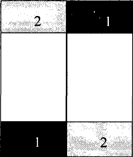
[0138] Assume that the PUCCH is reserved as Figure 4 Four uplink control signaling resource units are shown. In a certain uplink subframe, ...
Embodiment 2
[0166] It is assumed that user data can only occupy RB resources reserved for PUCCH in the following three modes. Mode 1, for all VRBs allocated to user data containing reserved RB resources on the PUCCH upper sideband, the user equipment can only use the RB resources of the corresponding VRB in the first half of the subframe; for all reserved RB resources including PUCCH lower sideband allocated to user data For the VRB resource, the user equipment can only use the RB resource corresponding to the VRB in the second half of the subframe. Mode 2: For all VRBs allocated to user data that contain reserved RB resources on the PUCCH upper sideband, the user equipment can only use RB resources corresponding to the VRB in the second half of the subframe; for all VRBs allocated to user data that contain reserved PUCCH lower sideband For the VRB of the RB resource, the user equipment can only use the RB resource corresponding to the VRB in the first half of the subframe. In mode 3, for ...
PUM
 Abstract
Description
Claims
Application Information
PatSnap Eureka turns technology decisions into work you can execute. Powered by our Innovation Knowledge Graph, it runs expert workflows across engineering, life sciences, materials and intellectual property. Get your review-ready output in minutes.


