Method for releasing resource, terminal, network side equipment and network system

A technology for network side equipment and resource release, which is applied in the fields of resource release, network side equipment and network systems, and can solve problems such as a resource release method that does not provide HS-RACH

Active Publication Date: 2009-07-01
HUAWEI TECH CO LTD
View PDF0 Cites 24 Cited by
  • Summary
  • Abstract
  • Description
  • Claims
  • Application Information

AI Technical Summary

Problems solved by technology

[0005] In the prior art, a scheme of using HS-RACH instead of RACH to realize uplink transmission

Method used


Image

  • Method for releasing resource, terminal, network side equipment and network system
  • Method for releasing resource, terminal, network side equipment and network system
  • Method for releasing resource, terminal, network side equipment and network system

Examples


Embodiment 1

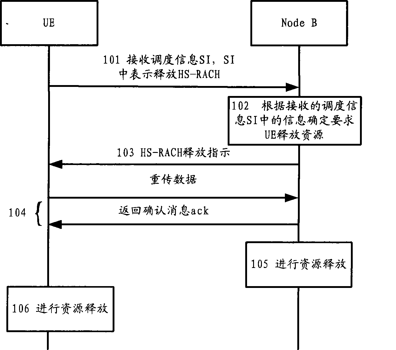
[0036] see figure 1 , is a flow chart of a resource release method according to an embodiment of the present invention, and the application scenario is that the UE does not need to change states, and the cell does not change.

[0037] figure 1 Include steps in:

[0038] Step 101, the Node B receives the scheduling information SI sent by the UE;

[0039] During the period when UE uses HS-RACH to send uplink data, it will send SI to Node B periodically or when there is a new data request to send, and SI carries the data buffer capacity of UE;

[0040] The scheduling information SI can be transmitted separately, or carried in uplink data for transmission.

[0041] Step 102, the Node B determines to require the UE to release resources according to the information in the received scheduling information SI;

[0042] When the Node B finds that the data buffer occupancy indicated in the SI is lower than a certain threshold or is 0, it decides to request the UE to release resources...

Embodiment 3

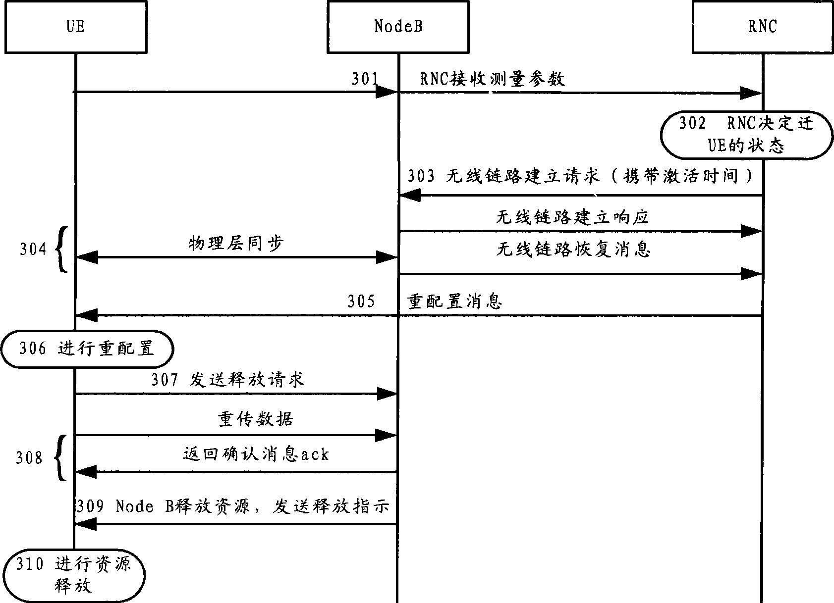
[0100] see Figure 4 , is a flow chart of the resource release method according to Embodiment 3 of the present invention, and the application scenario is that the UE does not perform state transition but needs to perform cell replacement.

[0101] Figure 4 Include steps in:

[0102] Step 401, the UE uses the HS-RACH to send uplink data in the current cell;

[0103] Step 402: After the UE measures and finds that the cell reselection condition is satisfied, it decides to perform cell reselection;

[0104] The cell reselection conditions mentioned here, for example, the signal quality of the same frequency cell is relatively poor and the cell with good signal quality needs to be reselected, etc. Suppose the UE is in the original cell 1 and finds that the signal quality of cell 2 is better than cell 1, and decides to update the cell. to cell 2.

[0105] Step 403, the UE sends a release request to the Node B of the original cell 1;

[0106] The release request sent by the UE ...

Embodiment approach 1

[0160] The terminal 1001 is configured to acquire trigger information, determine to release the allocated HS-RACH resources according to the acquired trigger information, and release the allocated HS-RACH resources at the local end after the determination to release the allocated HS-RACH resources . The network side device 1002 is configured to release the allocated HS-RACH resource at the local end after learning that the terminal 1001 determines to release the allocated HS-RACH resource.


PUM


Abstract

The embodiment of the invention discloses a method for releasing resources, which comprises the following steps: obtaining triggering messages; determining and releasing high-speed random access channel HS-RACH resources distributed according to the obtained triggering messages; and releasing the HS-RACH resources distributed on a network side and in the terminal respectively. Accordingly, the embodiment of the invention further provides network side equipment, the network side equipment comprises a message obtaining unit used for obtaining the triggering messages; a decision-making unit used for determining and releasing the HS-RACH resources distributed according to the obtained triggering messages; a processing unit used for releasing the HS-RACH resources distributed at the terminal after determining and releasing the HS-RACH resources distributed through the decision-making unit. The embodiment of the invention further provides a terminal and a network system. The embodiment of the invention provides the technical scheme which solves the problem of releasing the HS-RACH resources.

Description

technical field [0001] The present invention relates to the field of communication technologies, and in particular to a resource release method, a terminal, a network side device and a network system. Background technique [0002] In the current communication network, in order to reduce the uplink signaling transmission delay and discontinuous data packet transmission delay, the existing random access is improved, and the enhanced HS-RACH (high speed Random Access Channel, high speed random access channel) is proposed. channel) instead of RACH (Random Access Channel, random access channel) to realize the scheme of uplink transmission. [0003] In the scheme proposed in the prior art, the enhanced random access process mainly includes: when the terminal UE receives a response through the AICH (Acquisition Indicator Channel, Acquisition Indicator Channel), the Node B (Node B) sends the uplink resource allocation through the downlink channel A message is sent to the accessing ...

Claims


Application Information

Patent Timeline
IPC IPC(8): H04W74/08H04W76/02H04W76/06H04W88/02
CPCH04L47/76H04W76/06H04W72/00H04W76/068H04W76/30H04W74/0833H04W72/04H04W76/38
Inventor 马洁贺传峰
Owner HUAWEI TECH CO LTD
Why Eureka
Try Eureka