Convex column structure and electronic apparatus housing using the same
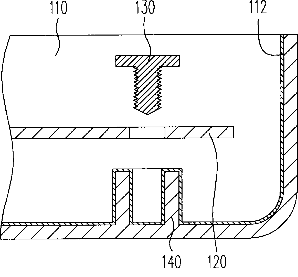
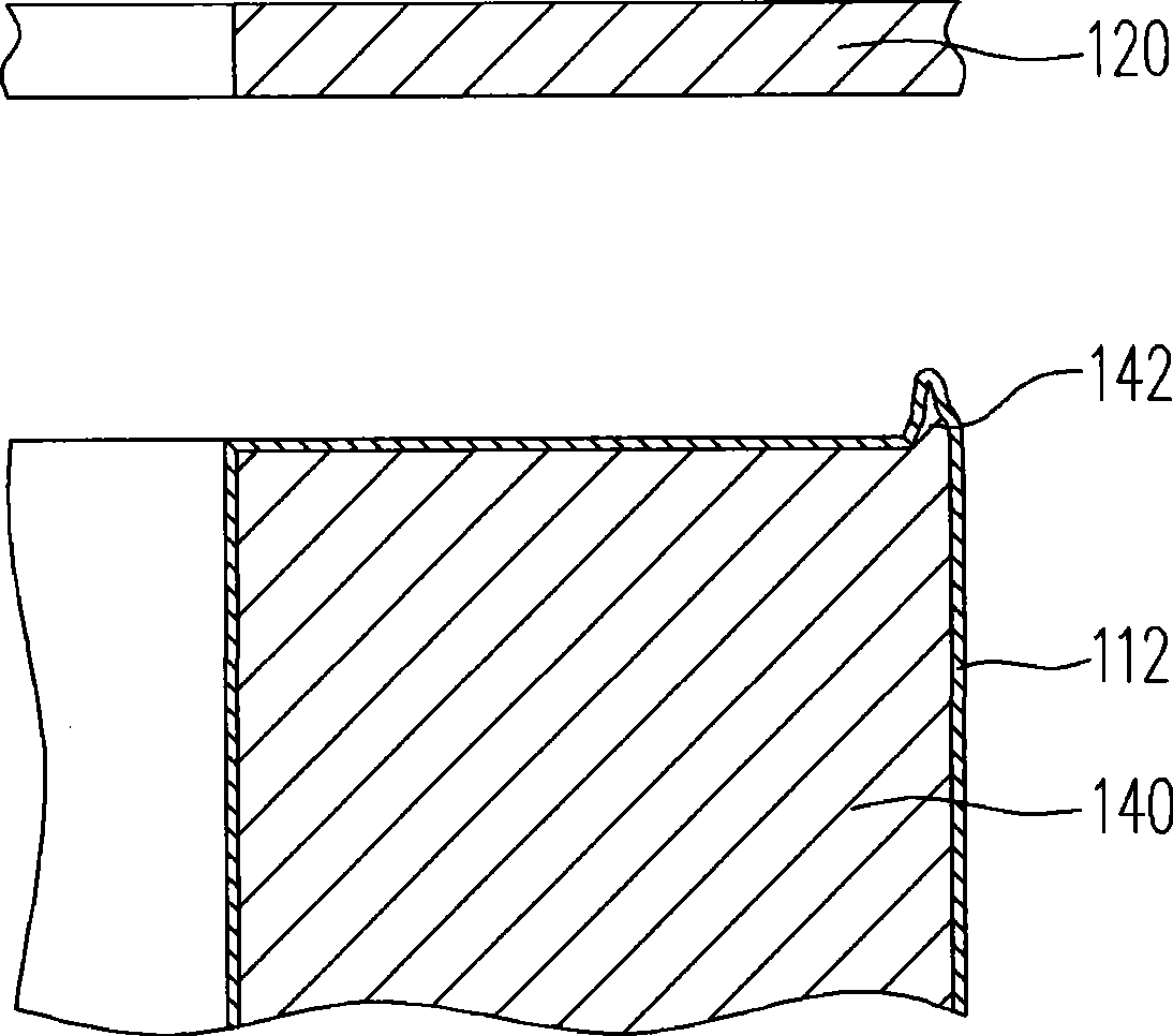
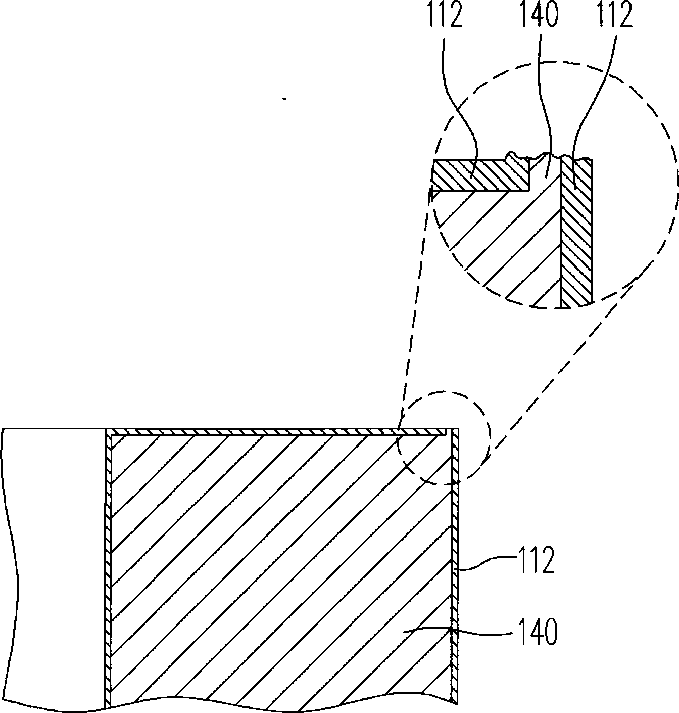
A technology of electronic devices and protrusions, which is applied in the direction of casing/cabinet/drawer parts, electrical components, magnetic field/electric field shielding, etc., and can solve the problem of destroying the integrity of the metal layer 112
- Summary
- Abstract
- Description
- Claims
- Application Information
AI Technical Summary
Problems solved by technology
Method used
Image
Examples
no. 1 example
[0048] Please refer to image 3 and Figure 4A , image 3 is a structural schematic diagram of an electronic device casing according to the first embodiment of the present invention, and Figure 4A for image 3 The partially enlarged schematic diagram of the convex column structure in . The electronic device case 200 includes a wall 210 , a protrusion 220 a and a metal layer 230 . The boss 220a is connected to the inner surface of the wall 210, and has a plane 222a at the top of the boss 220a and a chamfer 224 connecting the plane 222a, and the metal layer 230 covers the exposed part of the wall 210. The inner surface and the exposed surface of the protrusion 220a, and the protrusion 220a and the metal layer 230 covering the surface of the protrusion 220a form a protrusion structure 240a.
[0049] In the first embodiment, the chamfer 224 is, for example, a chamfer, and the material of the wall body 210 and the protrusion 220a is, for example, plastic, and the wall body 21...
no. 2 example
[0053] Please refer to Figure 4B , Figure 4B It is a partially enlarged schematic view of the protrusion structure in the second embodiment of the present invention. The protrusion structure 240b in the second embodiment is similar to the protrusion structure 240a in the first embodiment. The difference between the two is that the protrusion 220b of the protrusion structure 240b further has a shoulder 222c, and the shoulder 222c is away from the plane 222a and connected to the plane 222a via the chamfer 224 . At this time, the burr 226 formed on the boss 220b after the mold is removed is located between the shoulder 222c and the outer surface 222b of the boss 220b, so that the height of the burr 226 will be lower than the top plane 222a of the boss 220b.
no. 3 example
[0055] Please refer to Figure 4C , Figure 4C It is a partially enlarged schematic view of the protrusion structure in the third embodiment of the present invention. The protrusion structure 240c in the third embodiment is similar to the protrusion structure 240a in the first embodiment. The difference between the two lies in that the chamfer 224 of the protrusion 220 a in the first embodiment is a chamfer, while the chamfer 224 of the protrusion 220 c in the third embodiment is a rounded corner.
PUM
 Abstract
Description
Claims
Application Information
 - R&D Engineer
- R&D Manager
- IP Professional
- Industry Leading Data Capabilities
- Powerful AI technology
- Patent DNA Extraction
Browse by: Latest US Patents, China's latest patents, Technical Efficacy Thesaurus, Application Domain, Technology Topic, Popular Technical Reports.
© 2024 PatSnap. All rights reserved.Legal|Privacy policy|Modern Slavery Act Transparency Statement|Sitemap|About US| Contact US: help@patsnap.com


