Novel clock
A watch, a new type of technology, applied in the field of watches and clocks, can solve problems such as not getting rid of the way of expression
- Summary
- Abstract
- Description
- Claims
- Application Information
AI Technical Summary
Problems solved by technology
Method used
Image

Examples
Embodiment 1
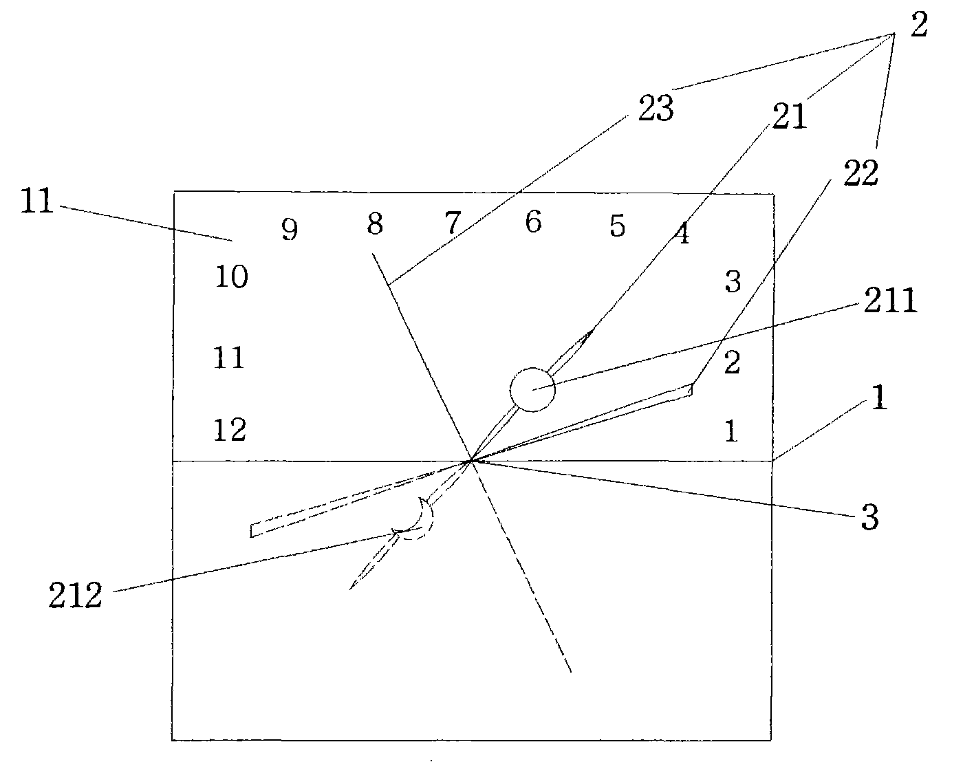
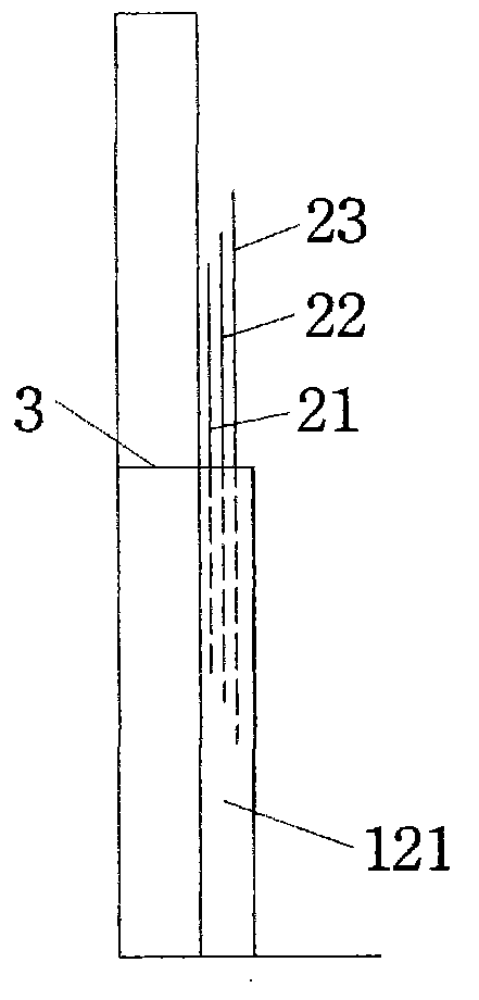
[0024] Such as figure 1 As shown, a new type of timepiece includes a clock face 1, a pointer 2 and a time component. The time component drives the pointer 2 to move around the pointer axis on the clock face. The clock face 1 is divided into a scale part 11 and a non-internal and external positional relationship. Scale part 12, scale part 11 Peripheral distribution time mark, instant scale: 1-12, minute and second scale: 1-60; the pointer moves in the scale part according to the law of time and points to the corresponding time mark; the pointer includes an hour hand 21. Minute hand 22, second hand 23.
[0025] The time-travel assembly is provided with a reset device for the pointer 2 so that it can quickly return to the starting position of the scale when the pointer 2 finishes the scale part.
[0026] In the reset device, the pointer shaft 3 is set at the center point of the pointer 2, so that one end of the pointer 2 has finished the clock face scale, and the other end just points...
Embodiment 2
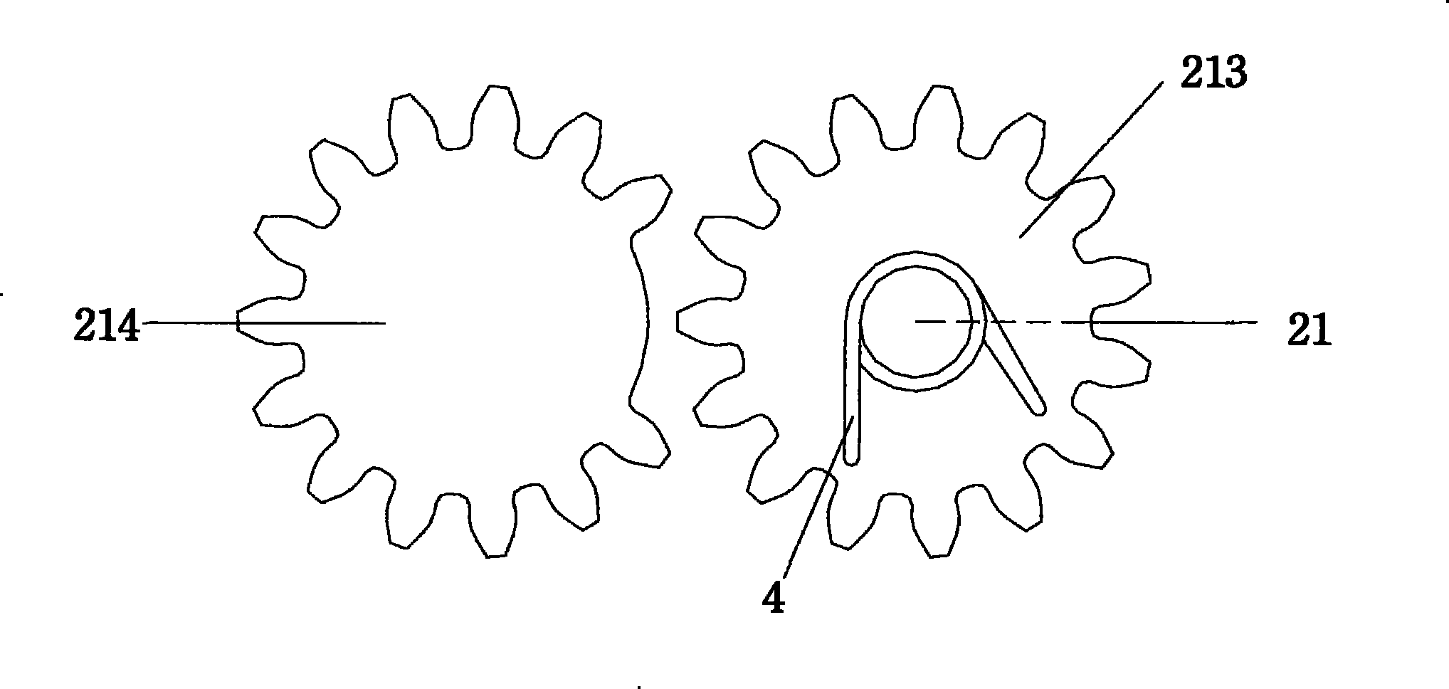
[0030] Such as image 3 As shown, the reset device in Embodiment 1 can adopt a mechanical structure. The time-travel assembly includes a gear set, and the reset device is one or more gears with missing teeth in the gear set, the missing teeth range and other The matching relationship of the gears satisfies: when the pointer runs through the scale part of the clock face, the pointer can quickly and just finish the non-time part.
[0031] The working principle of the structure: the hour hand 21 is taken as an example. The time component of the hour hand 21 includes an over wheel 214 and an output wheel 213. The over wheel 214 is provided with a certain number of missing teeth. The output wheel 213 is provided with a torsion spring 4 and the hour hand 21 It rotates synchronously with the output wheel 213; between the hour hand 21 from 1 o'clock to 12 o'clock, the toothed part of the wheel 214 meshes with the output wheel 213, and the torsion spring 4 is forced to rotate to generate t...
Embodiment 3
[0033] Such as Figure 4 As shown, the reset device in Embodiment 1 can adopt another mechanical structure. The time component includes a drive gear and an output gear, the output gear drives the pointer to rotate; the reset device is a clutch, and the clutch is connected to the drive gear. The driving gear meshes with the output gear when the pointer passes through the scale part of the clock face, and the driving gear is separated from the output gear when the pointer goes through the scale part, and the pointer returns to the starting point of the scale part of the clock face through the mechanical structure.
[0034] The working principle of this structure: Taking the hour hand 21 as an example, the hour hand travel time component includes a driving wheel 215 and an output wheel 213. The driving wheel 215 and the output wheel 213 are transmitted by a clutch 5, which is a longitudinally movable, axial In the rotating pinion wheel, a torsion spring 4 is provided in the output wh...
PUM
 Abstract
Description
Claims
Application Information
 - R&D
- Intellectual Property
- Life Sciences
- Materials
- Tech Scout
- Unparalleled Data Quality
- Higher Quality Content
- 60% Fewer Hallucinations
Browse by: Latest US Patents, China's latest patents, Technical Efficacy Thesaurus, Application Domain, Technology Topic, Popular Technical Reports.
© 2025 PatSnap. All rights reserved.Legal|Privacy policy|Modern Slavery Act Transparency Statement|Sitemap|About US| Contact US: help@patsnap.com