Movie mode video signal detection method

A film mode and detection method technology, applied in the direction of TV, electrical components, image communication, etc., to achieve fast switching, wide adaptability, and self-adaptive effects

Inactive Publication Date: 2009-07-15
SICHUAN PANOVASIC TECH
View PDF0 Cites 9 Cited by
  • Summary
  • Abstract
  • Description
  • Claims
  • Application Information

AI Technical Summary

Problems solved by technology

[0011] The technical problem to be solved by the present invention is to provide a movie mode video signal detection method in view of the shortcomings of the existing technology that the threshold value is fixed, and cannot adapt to the video with large field difference fluctuations and the video signal with only a small amount of motion information. Can overcome above-mentioned shortcoming of prior art

Method used


Image

  • Movie mode video signal detection method
  • Movie mode video signal detection method
  • Movie mode video signal detection method

Examples


Embodiment

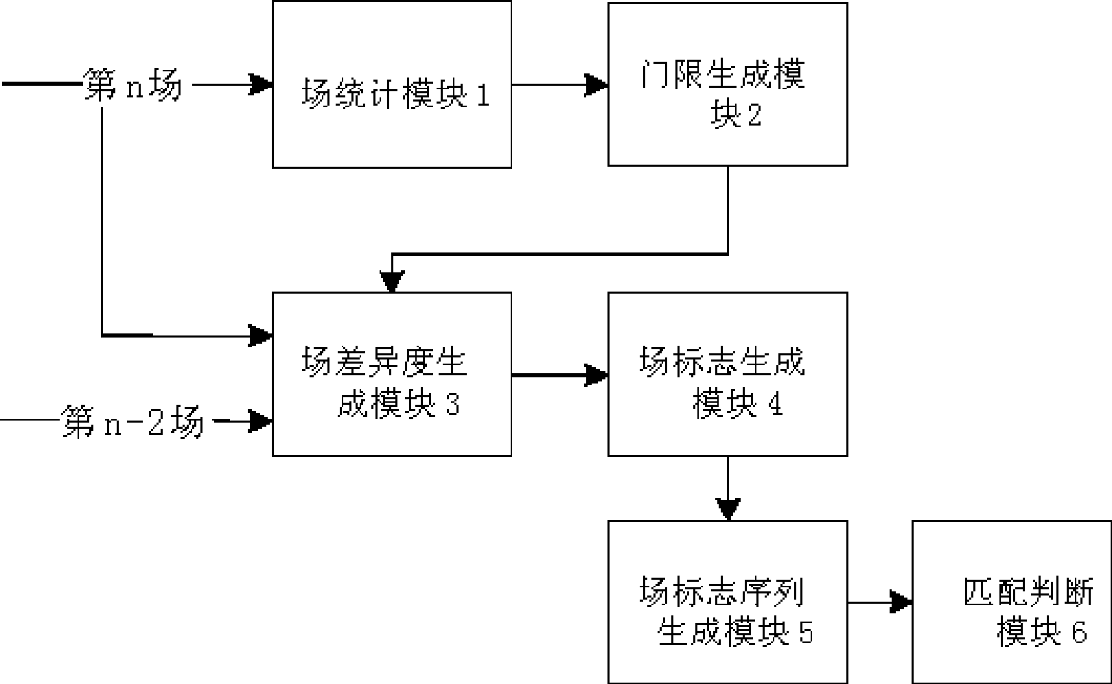
[0042] Such as figure 2 As shown, the present invention detects the system of film mode to comprise field statistics module 1, threshold generation module 2, field difference degree generation module 3, field mark generation module 4, field mark sequence generation module 5 and match judgment module 6, and this system judges input The specific steps to determine whether the video is in movie mode are as follows:

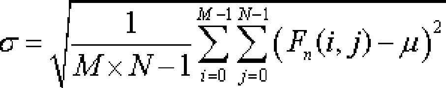
[0043] 1. Input the current field data into field statistics module 1, and count the mean value and mean square error μ and σ of the current field:

[0044] μ = 1 M × N Σ i = 0 M - 1 Σ j = 0 N - 1 ...


PUM


Abstract

The invention, relating to a method of recognizing whether an input video is a 3:2 drop-down film mode or a common interlacing scan video, claims a method for detecting video signals in film mode, aiming at the defects of fixed threshold in existing technology, un-adaptation of video with great fluctuation of field difference and the existence of video signals with a little movement information. The method for detecting film modes of the invention is based on that every seven continuous input fields of the interlacing signals in film mode all contain a pair of copying fields which are totally the same in theory; a 5bits sequence is obtained by counting diversity of a field difference which is the nearest to the homopolar filed in the seven continuous fields; the sequence is compared with a standard sequence group in film mode; current field is judged to be the video filed in film mode if they are the same, otherwise, current field is judged to be a filed not in film mode. The invention is mainly used in de-interlacing process field of television signals.

Description

technical field [0001] The invention relates to an interlaced video scanning format conversion technology, in particular to a method for identifying whether an input video is a 3:2 pull-down movie mode or a common interlaced scanning video. technical background [0002] Due to the limitation of transmission bandwidth, the video signal sent by the TV station is not a complete image, but a frame is divided into odd field and even field and transmitted successively. At the user terminal, the TV is also scanned one by one. , to realize the display of the image. This technology is called interlaced scanning technology, although it saves transmission bandwidth, it damages the picture quality. With the continuous development of TV technology and the continuous improvement of the audience's requirements for the picture quality of watching TV programs, progressive scan TVs have become popular, but the TV signals sent by broadcasting stations are still dominated by interlaced scan si...

Claims


Application Information

Patent Timeline
Patent Type & Authority Applications(China)
IPC IPC(8): H04N17/00H04N7/01
Inventor 刘强陈涛
Owner SICHUAN PANOVASIC TECH
Why Eureka
Try Eureka