Inorganic phosphor

A technology of inorganic fluorescence and main body, applied in the field of inorganic phosphors, which can solve the problems of low absolute light quantity, small light-emitting area, and limited use.

Inactive Publication Date: 2009-07-22
FUJIFILM CORP
View PDF4 Cites 3 Cited by
  • Summary
  • Abstract
  • Description
  • Claims
  • Application Information

AI Technical Summary

Problems solved by technology

In addition, inorganic fluorescent devices are similar to LEDs driven in the same way, both of which are made of inorganic materials, but because the light-emitting surface of the LED is extremely small, that is, point light is generated, so although the brightness per unit area is high, the absolute light quantity ( luminous flux) less
So LEDs are of limited use

Method used


Image

  • Inorganic phosphor

Examples


Embodiment 1

[0070] For every 100g ZnS, weigh Ir 2 (SO 4 ) 3 And mix with ZnS so that the amount of Ir element relative to the amount of Zn element is as follows. After mixing in a mortar for 20 minutes or more, it was calcined at 1100° C. for 3 hours in a vacuum. After calcination, the product was pulverized, washed with water and dried to obtain an Ir-containing ZnS phosphor.

[0071] The wavelength and intensity of light emitted by photoluminescence (PL) when the obtained phosphor was excited with ultraviolet rays of 330 nm are shown in Table 1 below.

[0072] Table 1

[0073] Ir 2 (SO 4 ) 3 doping amount PL emission wavelength PL luminous intensity Remark Sample A 0 Not illuminated Not illuminated comparative example Sample B 1E-7mol / molZn 445nm 100 this invention Sample C 1E-6mol / molZn 445nm 800 this invention Sample D 1E-5mol / molZn 445nm 3200 this invention Sample E 1E-4mol / molZn 445nm 1800 this in...

Embodiment 2

[0077] To sample D in Example 1 above, Group XIII-XV compounds were added and mixed in the addition amounts shown below, followed by calcination at 700° C. for 6 hours in vacuum. The results are shown in Table 2 below.

[0078] Table 2

[0079] Ir 2 (SO 4 ) 3 doping amount Doping amount of Group XIII-XV compounds Sample I 1E-5mol / molZn InP; 2E-4mol / molZn Sample J 1E-5mol / molZn InSb; 2E-4mol / molZn Sample K 1E-5mol / molZn GaN; 2E-4mol / molZn

[0080] It can be seen that the luminescence caused by Ir doping is further enhanced by adding a Group XIII-XV compound (including elements of Group 13 and Group 15 of the periodic table). Especially in the case of adding InSb, the PL luminous intensity is the highest.

Embodiment 3

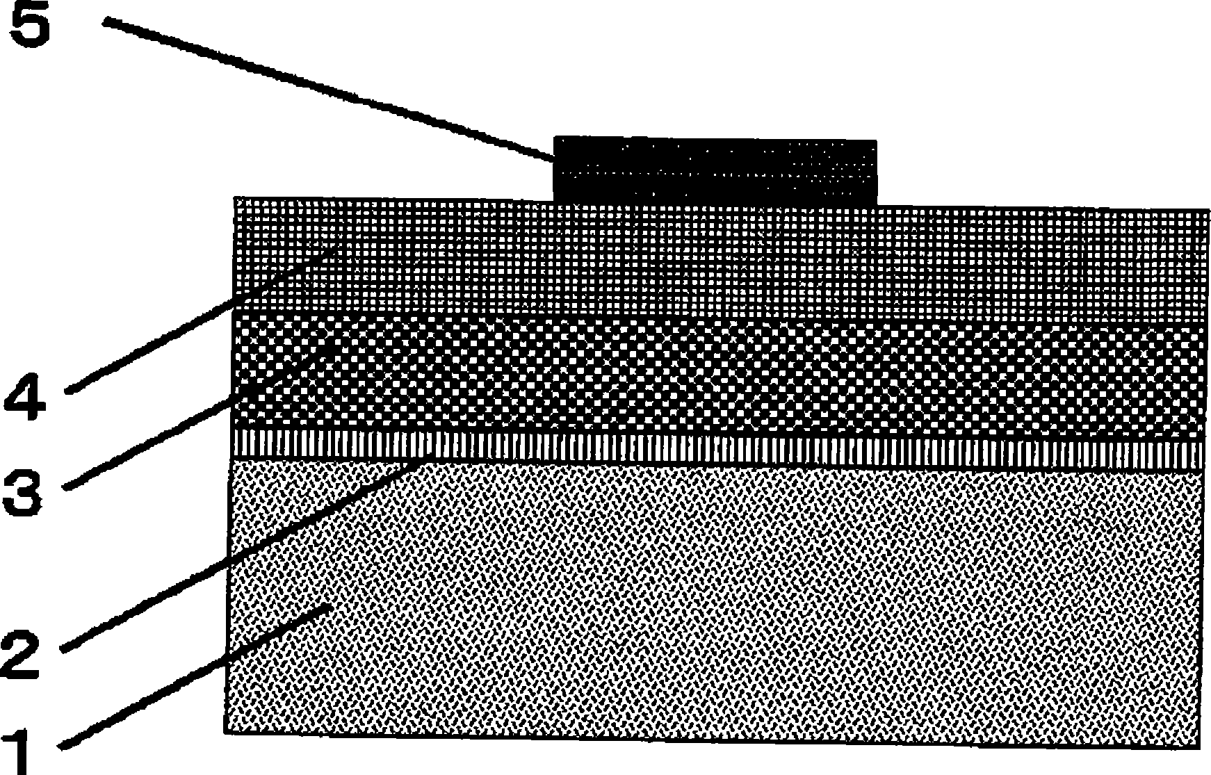
[0082] A DC-driven inorganic EL element was prepared using the inorganic phosphors of Sample D and H to K obtained in Examples 1 and 2 as inorganic fluorescent materials. A schematic structure of a DC-driven inorganic EL element is shown in figure 1 shown.

[0083] Using a transparent glass substrate 1 on which a 200nm-thick ITO as the first electrode 2 was formed by sputtering as a substrate, the inorganic phosphors of samples D and H to K were vacuum-coated by EB vacuum deposition equipment. deposited to form a film on the substrate. More specifically, the inorganic phosphor is set as the first vacuum deposition source, and metal selenium is set as the second vacuum deposition source. Vacuum deposition is performed at a constant film formation rate from the first vacuum deposition source, and for vacuum deposition from the second vacuum deposition source, the first luminescence is formed by making the weight ratio of selenium 0.5% or less in the first half of film formatio...


PUM

PropertyMeasurementUnit
thicknessaaaaaaaaaa
thicknessaaaaaaaaaa

Abstract

An inorganic phosphor includes: a host material that contains at least one host compound selected from the group consisting of compounds of group 2 element with group 16 element of the periodic table and compounds of group 12 element with group 16 element of the periodic table, or a mixed crystal of the host compound; and a dopant that includes at least one metal element selected from the group consisting of first metal elements belonging to second transition series of from group 6 to group 11 of the periodic table and second metal elements belonging to third transition series of from group 6 to group 11 of the periodic table, and does not include Cu and Mn.

Description

technical field [0001] The present invention relates to inorganic phosphors (hereinafter also referred to as inorganic fluorescent materials) that can be used in, for example, AC dispersion inorganic EL elements, AC thin film inorganic EL elements, and DC thin film inorganic EL elements. Background technique [0002] Fluorescent materials refer to materials that emit light when energy (such as light, electricity, pressure, heat, electron beams) is applied thereto, and are already known materials. Among them, fluorescent materials including inorganic materials have been applied to television picture tubes, fluorescent lamps, electroluminescent (EL) elements, and the like due to their light emitting properties and stability. In recent years, its application for low-speed electron excitation has been intensively studied, such as in PDPs as a color conversion material in LEDs. [0003] Electroluminescent (EL) elements using inorganic phosphors are roughly classified into AC-dri...

Claims


Application Information

Patent Timeline
Patent Type & Authority Applications(China)
IPC IPC(8): C09K11/87H05B33/14
CPCC09K11/876H05B33/18C09K11/873C09K11/567H05B33/14C09K11/883C09K11/565C09K11/885C09K11/75C09K11/88
Inventor 白田雅史
Owner FUJIFILM CORP
Why Eureka
Try Eureka