Electrostatic discharging protection circuit

An electrostatic discharge protection, circuit technology, applied in emergency protection circuit devices, emergency protection circuit devices for limiting overcurrent/overvoltage, circuit devices, etc.

Inactive Publication Date: 2009-07-22
RAYDIUM SEMICON
View PDF0 Cites 14 Cited by
  • Summary
  • Abstract
  • Description
  • Claims
  • Application Information

AI Technical Summary

Problems solved by technology

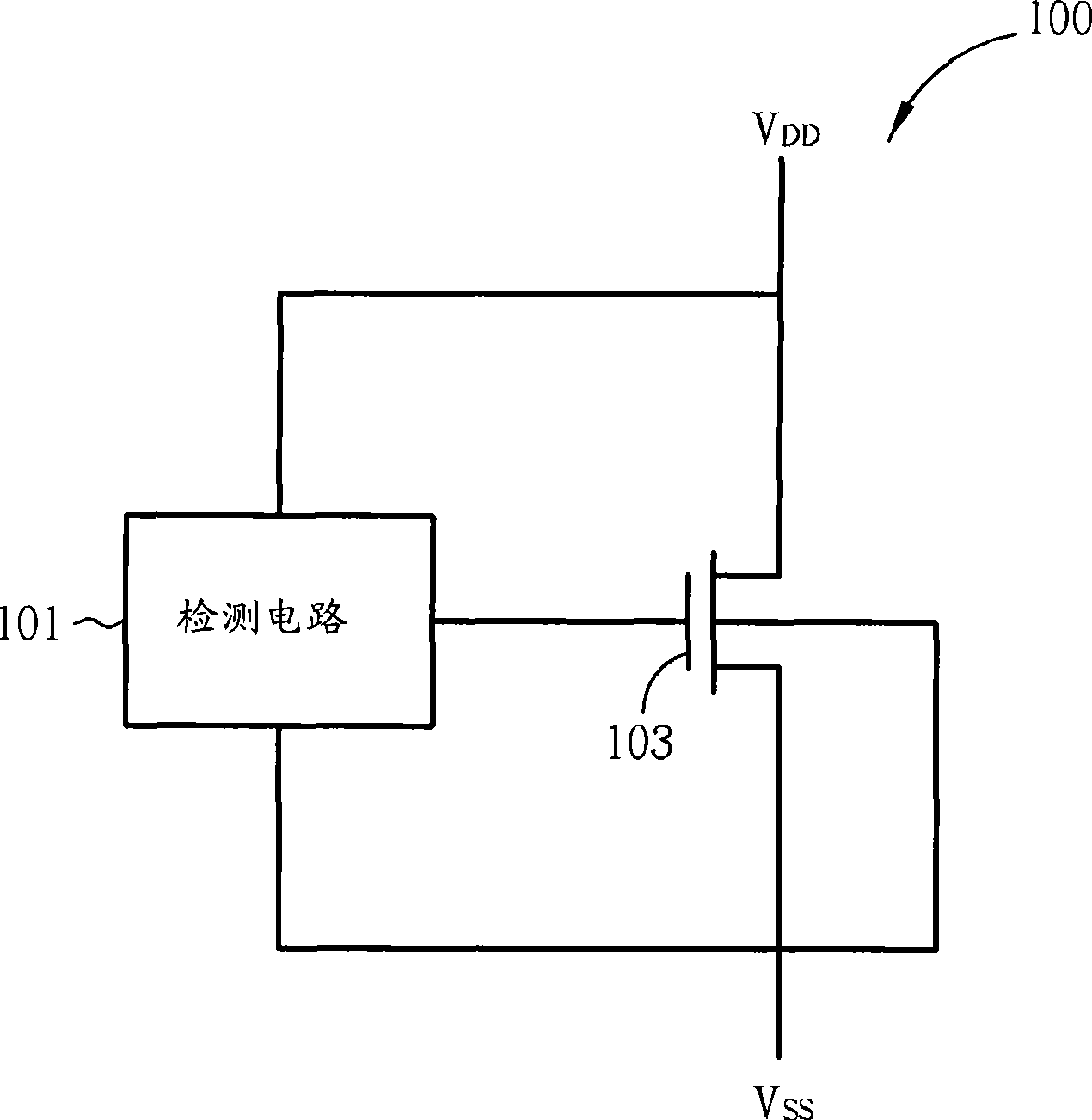
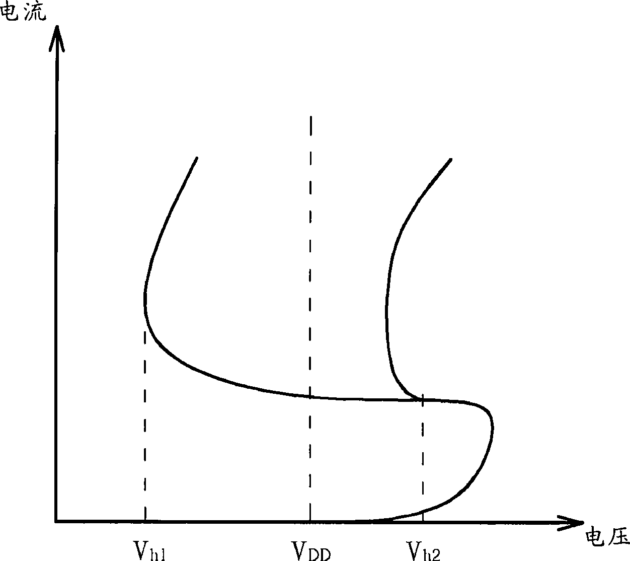
[0003] However, such a structure will cause the holding voltage of the NMOS transistor 103 to be lower than V when an ESD event occurs. DD , so that the NMOS transistor 103 is latch-up

Method used


Image

  • Electrostatic discharging protection circuit
  • Electrostatic discharging protection circuit
  • Electrostatic discharging protection circuit

Examples


Embodiment Construction

[0012] Certain terms are used in the specification and appended claims to refer to particular elements. Those of ordinary skill in the art should understand that hardware manufacturers may use different terms to refer to the same element. The description and the appended claims do not use the difference in name as a way to distinguish components, but use the difference in function of components as a criterion for distinguishing. The "comprising" mentioned in the entire specification and the appended claims is an open term, so it should be interpreted as "including but not limited to". In addition, the term "coupled" in this document includes any direct and indirect means of electrical connection. Therefore, if it is described herein that a first device is coupled to a second device, it means that the first device may be directly electrically connected to the second device, or indirectly electrically connected to the second device through other devices or connection means.

...


PUM


Abstract

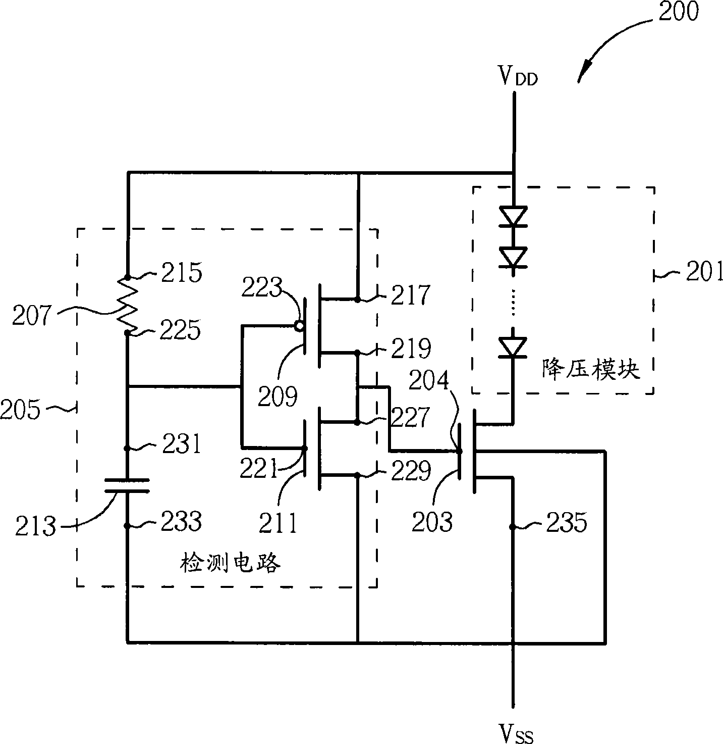
A static discharge protection circuit comprises: a step-down module that is coupled between a first voltage level and a second voltage level, wherein the first voltage level is higher than the second voltage level; a grid trigger switch that is coupled between the first voltage level and the second voltage level; and a detection circuit that is coupled with the grid trigger switch and used for detecting static discharge events so as to control the grid trigger switch.

Description

technical field [0001] The present invention relates to an electrostatic discharge protection circuit, in particular to an electrostatic discharge protection circuit with high sustain voltage. Background technique [0002] figure 1 A prior art electrostatic discharge protection circuit 100 is shown. Such as figure 1 As shown, the ESD protection circuit 100 includes a detection circuit 101 and an NMOS transistor 103 . The detection circuit 101 is used to detect an ESD event to control the NMOS transistor 103, and the NMOS transistor 103 is used as a switch. Generally speaking, the detection circuit 101 includes a circuit composed of a capacitor and a resistor, and uses the delay characteristics of the capacitor and resistor to control the NMOS transistor 103 according to the electrostatic discharge event. [0003] However, such a structure will cause the holding voltage of the NMOS transistor 103 to be lower than V when an ESD event occurs. DD , so that the NMOS transist...

Claims


Application Information

Patent Timeline
IPC IPC(8): H02H9/00H02H9/04
Inventor 吴坤泰杨景荣
Owner RAYDIUM SEMICON
Why Eureka
Try Eureka