
Semiconductor device and method for manufacturing the same

a technology of semiconductors and integrated circuits, applied in the direction of semiconductor devices, electrical equipment, transistors, etc., can solve the problems of parasitic scr elements turning, increasing the chip size of integrated circuits, and affecting the reliability of semiconductor devices, so as to prevent the latching of integrated circuits

Active Publication Date: 2011-09-20
DONGBU HITEK CO LTD
View PDF4 Cites 6 Cited by
  • Summary
  • Abstract
  • Description
  • Claims
  • Application Information

AI Technical Summary

Benefits of technology

[0013]It is one object of the present invention to provide a semiconductor device and a method for manufacturing the same, capable of preventing latchup of integrated circuits without using a double guard ring.

Problems solved by technology

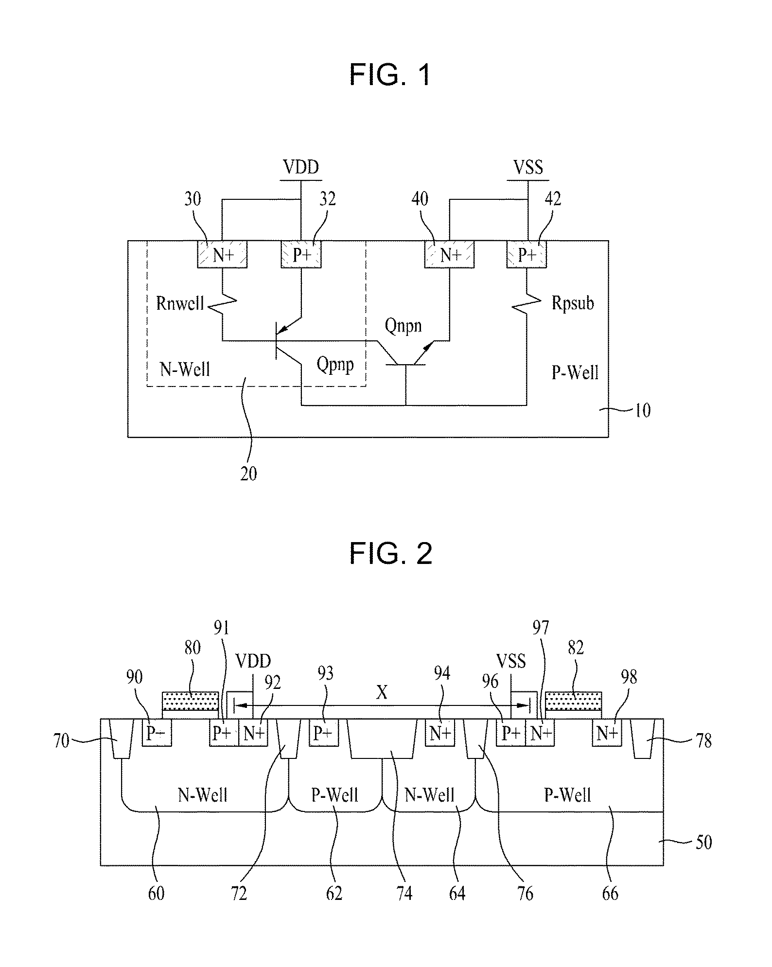
Such a parasitic SCR element may turn on, when semiconductor integrated circuits operate.
For this reason, important reliability problems may occur.
However, when an inner driver stage or core stage also adopts double guard rings, the chip size of integrated circuits increases.
For this reason, it is disadvantageous to apply the guard ring structure to the core stage.

Method used


Image

  • Semiconductor device and method for manufacturing the same
  • Semiconductor device and method for manufacturing the same
  • Semiconductor device and method for manufacturing the same

Examples


Embodiment Construction

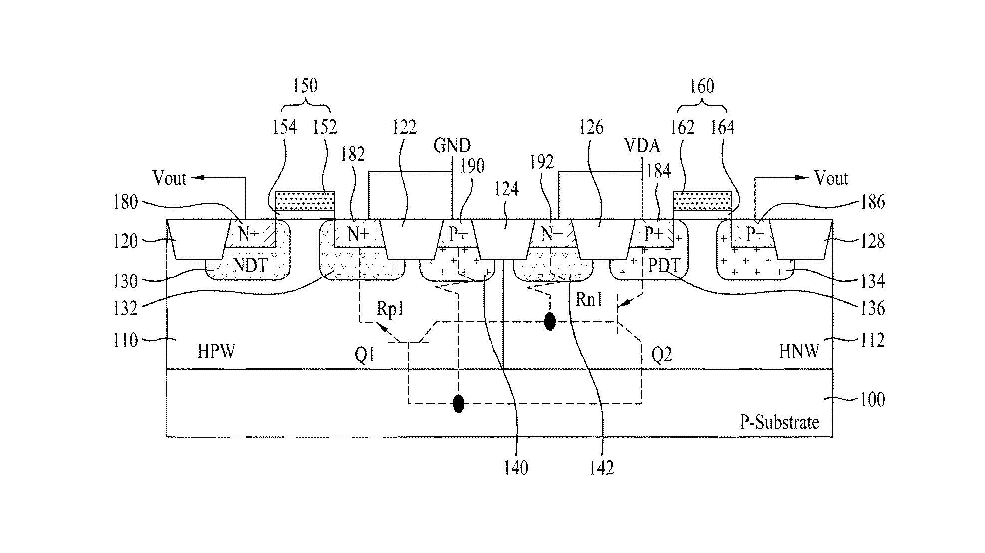
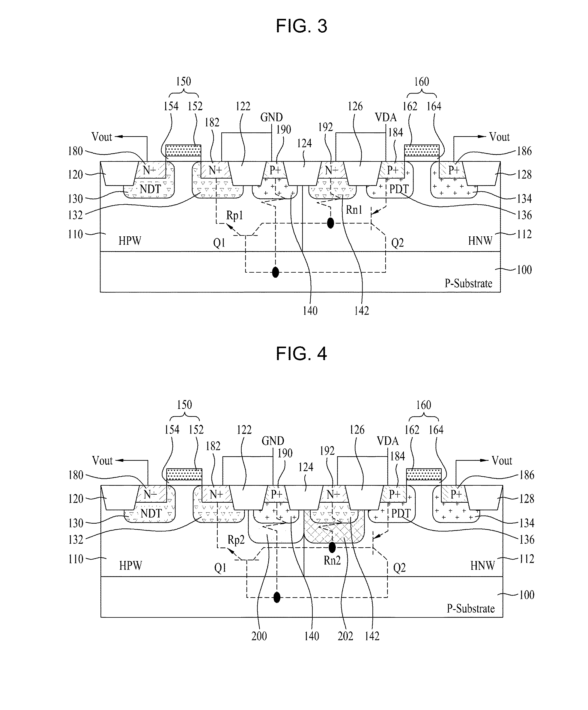
[0024]Hereinafter, although the present invention is described under the assumption that a first conductive-type mentioned in claims is a p-type and a second conductive-type is an n-type, the present invention is not limited thereto. That is, the present invention may be applied in the same manner under the assumption that the first conductive-type is an n-type and the second conductive-type is a p-type. In addition, even though the semiconductor device is described below as a p- or n-type high-voltage transistor, the present invention is not limited thereto. Furthermore, the semiconductor device may be included in an integrated circuit comprising at least one of the p- and n-type low-voltage transistors (and in a further embodiment, both of the p-type low-voltage transistor and the n-type low-voltage transistor).

[0025]Hereinafter, the semiconductor device will be described with conjunction to the accompanying drawings according to an exemplary embodiment of the present invention. F...


PUM


Abstract

Disclosed are a semiconductor device and a method for manufacturing the same. The semiconductor device includes at least two of first and second conductive-type high-voltage transistors and first and second conductive-type low-voltage transistors. The first conductive-type high-voltage transistor include a first conductive-type well in a semiconductor substrate, a device isolation film in the first conductive-type well, a gate pattern on the first conductive-type well, second conductive-type drift regions in the semiconductor substrate at opposite sides of the gate pattern, second conductive-type source and drain regions in the second conductive-type drift region, a pick-up region to receive a bias voltage, and a first latch-up inhibiting region under the pick-up region. Accordingly, it is possible to reduce and prevent latchup without using a double guard ring and to eliminate an additional process to form first and second latch-up inhibiting regions.

Description

[0001]This application claims the benefit of Korean Patent Application No. 10-2008-0108304, filed on Nov. 3, 2008, which is hereby incorporated by reference as if fully set forth herein.BACKGROUND OF THE INVENTION[0002]1. Field of the Invention[0003]The present invention relates to a semiconductor device and a method for manufacturing the same. More specifically, the present invention relates to semiconductor devices in an integrated circuit (IC) comprising high- and low-voltage transistors and a method for manufacturing such semiconductor devices.[0004]2. Discussion of the Related Art[0005]Source driver integrated circuits (ICs) are useful as display driver integrated circuits. Such source driver ICs vary slightly in power supply voltage regions, depending on the application(s) of the IC. Notebook computers have a low-voltage operational region of about 3.3V and a high-voltage operational region of about 13.5V. LCD TVs have a low-voltage operational region of about 3.3V and a high-...

Claims


Application Information

Patent Timeline
Patent Type & Authority Patents(United States)
IPC IPC(8): H01L29/76H01L31/119H01L31/062H01L31/113H01L29/94
CPCH01L21/823878H01L27/0921
Inventor KIM, SAN HONGKIM, JONG MIN
Owner DONGBU HITEK CO LTD
Learn More