Eureka AIR delivers breakthrough ideas for toughest innovation challenges, trusted by R&D personnel around the world.

Perpendicular magnetic recording head and method of manufacturing the same

A technology for perpendicular magnetic recording and manufacturing method, which is applied in the directions of magnetic recording heads, magnetic recordings, housings/shields of recording heads, etc., and can solve the problems of increased dispersion field, inability to increase track density, and inability to achieve high-density recording, etc. Achieving good recording characteristics and reducing the effect of scattered fields

Active Publication Date: 2009-07-29
WESTERN DIGITAL TECH INC
View PDF5 Cites 0 Cited by
  • Summary
  • Abstract
  • Description
  • Claims
  • Application Information

AI Technical Summary

Problems solved by technology

However, in these methods, the increase of the field strength usually leads to the expansion of the field, which causes the increase of the fringe field
Therefore, the track density cannot be increased, and of course high-density recording cannot be achieved.

Method used


Image

  • Perpendicular magnetic recording head and method of manufacturing the same
  • Perpendicular magnetic recording head and method of manufacturing the same
  • Perpendicular magnetic recording head and method of manufacturing the same

Examples


Embodiment Construction

[0048] Hereinafter, preferred embodiments of the present invention will be explained with reference to the drawings.

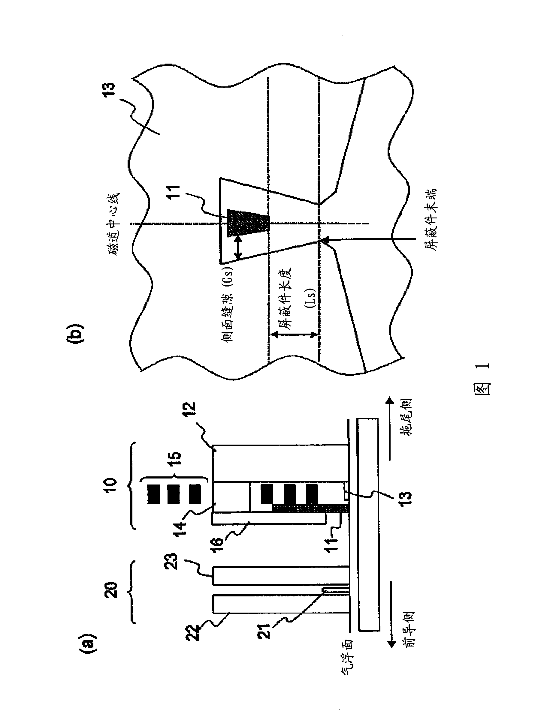
[0049] FIG. 1(a) shows a schematic cross-sectional view at the center line of the track, which illustrates an example of the magnetic head according to the present invention. The magnetic head is a recording / reproducing composite head that has a recording head 10 including a main pole 11 and an auxiliary pole 12, and a reproduction head 20 including a read element 21. For the reproduction head 20, a CIP-GMR element, a TMR element, or a CPP-GMR element, etc. is used, which is provided on a pair of magnetic components including a lower shield 22 on the leading side and an upper shield 23 on the trailing side. Between shields. The writing function part has a basic structure that includes a main pole 11 that performs writing to the disk, a position on the trailing side of the main pole, and a side of each side of the main pole in the cross-track direction. The shield ...


PUM


Abstract

Embodiments of the present invention provide a perpendicular magnetic recording head which can suppress reduction in recording field and efficiently reduce a fringe field. According to one embodiment, a side shield 13 disposed at a side of each side face in a cross track direction of a main pole 11 is arranged at a far leading side compared with the main pole.

Description

Technical field [0001] The present invention relates to a perpendicular magnetic recording head capable of providing a high recording field while suppressing the erasure of adjacent tracks, and a method of manufacturing the head. Background technique [0002] In order to achieve high recording density of HDD (Hard Disk Drive), the key point is to obtain a high field strength that enables recording on a medium with high thermal stability and does not induce deterioration of the recording pattern of adjacent tracks during high track density recording. The field distribution. However, the above two points often contradict each other. That is, in the head structure for generating a high magnetic field, the field expansion range in the track width direction is also large. On the other hand, as the track density increases, there will be a problem of signal degradation in adjacent tracks, which will occur during the recording process. This problem is a phenomenon that even if the leakag...

Claims


Application Information

Patent Timeline
Patent Type & Authority Applications(China)
IPC IPC(8): G11B5/31G11B5/127G11B5/11
CPCG11B5/1278G11B5/3116G11B5/3163G11B5/112G11B5/315G11B5/3146
Inventor 杉山干人星屋裕之布川功
Owner WESTERN DIGITAL TECH INC
Why Eureka
Eureka Blog
Learn More