Eureka AIR delivers breakthrough ideas for toughest innovation challenges, trusted by R&D personnel around the world.

Optical information recording medium and its manufacture method

A technology for recording media and optical information, applied in temperature recording method, optical recording carrier, recording/reproducing by optical method, etc., which can solve the problems of high cost and reduced corrosion resistance of light reflection layer

Inactive Publication Date: 2008-06-11
FUJIFILM CORP
View PDF39 Cites 0 Cited by
  • Summary
  • Abstract
  • Description
  • Claims
  • Application Information

AI Technical Summary

Problems solved by technology

However, if Ag is used in the light reflection layer, there will be a problem of high cost, and thus it will become a big problem when mass-producing the optical disc.
In addition, depending on the formation conditions, there is a problem that the corrosion resistance of the light reflection layer made of Ag decreases.

Method used


Image

  • Optical information recording medium and its manufacture method
  • Optical information recording medium and its manufacture method

Examples


Embodiment 1

[0069] On the surface of a substrate made of injection-molded polycarbonate resin having a spiral groove (groove depth: 30nm, groove width: 150nm, track pitch: 340nm) with a thickness of 1.1mm, an outer diameter of 120mm, and an inner diameter of 15mm , in an Ar atmosphere, a light reflection layer made of aluminum (Al: purity 99.9% by mass or more) was formed by DC sputtering. The detailed conditions of sputtering are described in Table 1.

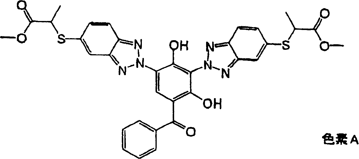
[0070] Then, 2 g of a dye represented by the following chemical formula was added to 100 ml of 2,2,3,3-tetrafluoropropanol and dissolved to prepare a dye coating solution. The pigment coating liquid was coated on the light reflection layer under the conditions of 23° C. and 50% RH by the spin coating method while changing the rotation speed from 300 rpm to 4000 rpm. Then, it was stored at 23° C. and 50% RH for 1 hour to form a recording layer (ingroove thickness: 100 nm, on groove thickness: 70 nm).

[0071] 【Chemical 1】

[0072]

...

Embodiment 2 to 5

[0086] Optical information recording media of Examples 2 to 5 were produced in the same manner as in Example 1 except that the conditions for forming the light reflection layer in Example 1 were changed as shown in Table 1.

[0087] The same test as in Example 1 was performed on the obtained optical information recording medium to evaluate recording characteristics. The results are shown in Table 1.

Embodiment 6 to 19

[0089] Under the conditions shown in Table 1 and an Ar atmosphere, DC sputtering was performed on a substrate made of an injection-molded polycarbonate resin (polycarbonate manufactured by Teijin Corporation; trade name panlaido AD5503) having a thickness of 1.1 mm. A light reflection layer made of aluminum or an aluminum alloy is formed on the surface of a spiral groove (groove depth: 40nm, groove width: 150nm, track pitch: 320nm) with an outer diameter of 120mm and an inner diameter of 15mm. In addition, in Example 7, the Ti content in the aluminum alloy (Al—Ti) was 2 at%.

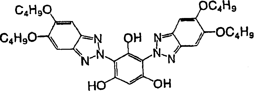
[0090] Then, 2 g of an organic substance represented by the following chemical formula was mixed with 100 ml of methyl lactate, and dissolved by ultrasonic treatment for 2 hours to prepare a pigment coating liquid. The pigment coating solution was coated on the light reflection layer under the conditions of 23° C. and 50% RH by the spin coating method while changing the rotation speed from 300 to 4000 rp...


PUM

PropertyMeasurementUnit
Layer thicknessaaaaaaaaaa
Surface roughnessaaaaaaaaaa
Thicknessaaaaaaaaaa

Abstract

An optical information recording medium including a substrate having a groove that has a track pitch of 200 to 400 nm and a depth of 10 to 150 nm, the substrate having successively disposed thereon a light-reflective layer, a recording layer and a cover layer, wherein information is recordable and reproducible by irradiating a laser beam having a wavelength of 500 nm or less from a side of the medium disposed with the cover layer, and the light-reflective layer contains aluminum or an aluminum alloy. The optical information recording medium which reduces a cost and has excellent recording characteristics by using a light reflection layer consisting of aluminum or aluminum alloy.

Description

technical field [0001] The invention relates to an optical information recording medium, in particular to a thermal mode add-on optical information recording medium. Background technique [0002] Heretofore, known are optical information media (optical discs) in which information can be recorded only once by laser light. The optical disc is also referred to as an add-on CD (so-called CD-R), and its typical structure is that a recording layer composed of an organic pigment and an optical layer composed of a metal such as gold are sequentially stacked on a transparent disc-shaped substrate. Reflective layer, protective layer of resin material. In addition, recording information on the CD-R is performed by irradiating the CD-R with laser light in the near-infrared region (usually a laser light with a wavelength around 780nm). Physical or chemical changes (such as groove formation), the optical properties of the part change, so that information recording takes place. In addit...

Claims


Application Information

Patent Timeline
IPC IPC(8): G11B7/24B41M5/26G11B7/007G11B7/244G11B7/258
CPCG11B7/24079G11B7/249G11B7/007G11B7/246G11B7/2478G11B7/258G11B7/24G11B7/2534G11B7/257G11B7/2585G11B7/2472G11B7/2467G11B7/248G11B7/2533Y10T428/21
Inventor 石田寿男宇佐美由久
Owner FUJIFILM CORP
Why Eureka
Eureka Blog
Learn More